


6 — ENG
DESCRIPTION OF OPERATION
It may be necessary to brace or support
one end of the outfit when attaching the
wheels and the rubber foot strip because
the air compressor will have a tendency to
tip.
TOOLS NEEDED FOR ASSEMBLY
• a 3/8" open end wrench or socket to tighten handle screws• a 9/16" socket or open end wrench for attaching the
wheels or removing shipping boards
THE WHEELS AND HANDLE DO NOT PRO-
VIDE ADEQUATE CLEARANCE, STABILITY OR
SUPPORT FOR PULLING THE UNIT UP AND
DOWN STAIRS OR STEPS. THE UNIT
MUST BE LIFTED, OR PUSHED UP A RAMP.
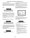
Installing Wheels, Handles, Rubber Foot
Strip
1. Attach the handle to the compressor saddle by inserting
the handle inside the compressor saddle and lining up the
two bolt holes on each side. Install the four screws, two on
each side. Tighten securely.
2. Install one shoulder bolt and one nut for each wheel using
upper bolt hole for 30 and 33 gallon units. Tighten
securely. The outfit will sit level if the wheels are properly
installed.
3. Clean and dry air tank leg opposite wheels. Remove the
protective paper strip from the adhesive backed rubber
foot strip. Attach the rubber foot strip to the bottom of leg.
Press firmly into place.
ASSEMBLY FOR (PORTABLE) COMPRESSORS
the motor is running, or continuous leaking after unit reaches
cut-out pressure.
Pressure Switch: The pressure switch automatically starts the
motor when the air tank pressure drops below the factory set
“cut-in” pressure. It stops the motor when the air tank pressure
reaches the factory set “cut-out” pressure.
Safety Valve: If the pressure switch does not shut off the air
compressor at its cut-out pressure setting, the safety valve will
protect against high pressure by “popping out” at its factory set
pressure (slightly higher than the pressure switch cut-out
setting).
Outlet Pressure Gauge: The outlet pressure gauge indicates
the air pressure available at the outlet side of the regulator. This
pressure is controlled by the regulator and is always less or
equal to the tank pressure.
Tank Pressure Gauge: The tank pressure gauge indicates the
reserve air pressure in the tank.
Regulator: The air pressure coming from the air tank is con-
trolled by the regulator knob. Turn the knob clockwise to
increase pressure and counterclockwise to decrease pressure.
To avoid minor readjustment after making a change in pressure
setting, always approach the desired pressure from a lower
pressure. When reducing from a higher to a lower setting, first
reduce to some pressure less than that desired, then bring up
to the desired pressure. Depending on the air requirements of
each particular accessory, the outlet regulated air pressure may
have to be adjusted while you are operating the accessory.
Cooling System: This compressor contains an advanced
design cooling system. At the heart of this cooling system is an
engineered fan. It is perfectly normal for this fan to blow air
through the vent holes in large amounts. You know that the
cooling system is working when air is being expelled.
Globe Valve: Turn the knob counter-clockwise to open the
valve and clockwise to close.
Drain Valve: The drain valve is located at the base of the air tank
and is used to drain condensation at the end of each use.
Motor Thermal Overload Protector: The electric motor has an
automatic thermal overload protector. If the motor overheats for
any reason, the thermal overload protector will shut off the
motor. The motor must be allowed to cool before restarting.
ON/AUTO - OFF Switch: Turn this switch ON to provide
automatic power to the pressure switch and OFF to remove
power at the end of each use.
Air Intake Filter: This filter is designed to clean air coming into
the pump. This filter must always be clean and ventilation
openings free from obstructions. See "Maintenance".
Air Compressor Pump: To compress air, the piston moves up
and down in the cylinder. On the downstroke, air is drawn in
through the air intake valves. The exhaust valve remains closed.
On the upstroke of the piston, air is compressed. The intake
valves close and compressed air is forced out through the
exhaust valve, into the outlet tube, through the check valve and
into the air tank. Working air is not available until the compres-
sor has raised the air tank pressure above that required at the
air outlet.
Check Valve: When the air compressor is operating, the check
valve is “open”, allowing compressed air to enter the air tank.
When the air compressor reaches “cut-out” pressure, the check
valve “closes”, allowing air pressure to remain inside the air
tank.
Pressure Release Valve: The pressure release valve located
on the side of the pressure switch, is designed to automatically
release compressed air from the compressor head and the
outlet tube when the air compressor reaches “cut-out” pressure
or is shut off. If the air is not released, the motor will try to start,
but will be unable to. The pressure release valve allows the
motor to restart freely. When the motor stops running, air will
be heard escaping from this valvefor a few seconds. No air
should be heard leaking when