16
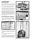
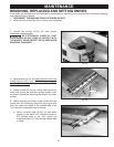
Fig. 30
OUTFEED TABLE
ADJUSTMENTS
For most jointing operations the outfeed table must be
exactly level with the knives at their highest point of
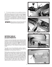
revolution. To move the outfeed table, loosen lock handle
(A)
Fig. 30, and move the table raising and lowering hand lever
(B) up or down until the table is level with the knives.
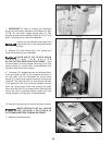
It may be necessary to adjust the positive stops. Loosen
the two locknuts (D) and (E) Fig. 31, and the two adjusting
screws (F) and (G) when moving the table up or down.
When the table is exactly level with the knives at the
highest point of revolution, tighten lock handle (A) Fig. 30,
and turn adjusting screw (F) Fig. 31, until it bottoms; then
tighten locknut (D). Screw (G) is also a positive stop for the
lower limit of the outfeed table. We suggest that this stop
also be tightened when the outfeed table is set level with
the knives. This will prevent the outfeed table from
accidently being lowered.
ADJUSTING BELT TENSION
The jointer is shipped with two V-belts assembled and
properly tensioned to the cutterhead and motor pulley. If
it becomes necessary to adjust belt tension, proceed as
follows:
B
A
Fig. 31
D
F
E
G
Fig. 32
Fig. 33
B
A
1. DISCONNECT THE MACHINE FROM THE POWER
SOURCE.
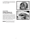
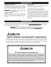
2. Pull outward on latch handle (A) Fig. 33, and open
hinged access door (B).
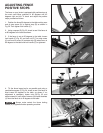
3. Fig. 31, illustrates the V-belts (C), motor pulley (D) and
cutterhead pulley (E). There should be approximately 1/2
inch deflection in the center span of the belts (C) using light
finger pressure. To adjust belt tension refer to STEP 4.
E
C
D


