


12
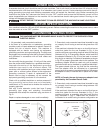
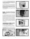
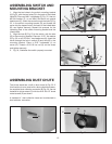
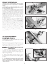
2. Fig. 18 illustrates fence properly mounted.
Fig. 18
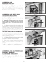
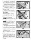
3. Thread shorter fence handle (E ) Fig.19, into infeed
end of fence (A) and longer fence handle (G) into outfeed
end as shown.
Fig. 19
E
G
A
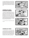
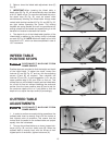
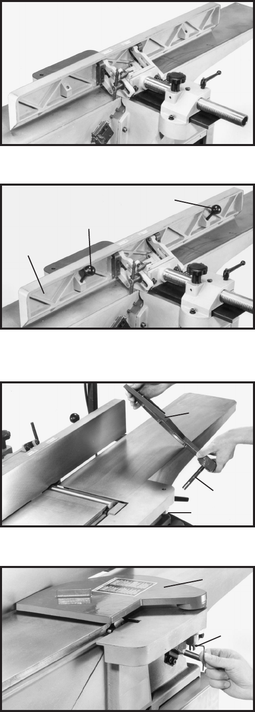
ASSEMBLING
CUTTERHEAD GUARD
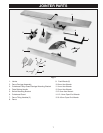
1. Remove set screw (not shown) from cutterhead
guard post (F) with the 2.5mm hex wrench. Insert post
(F) through hole in the infeed table. NOTE: A spring is
supplied in knob assembly (E) that returns the guard (C)
over the cutterhead after a cut has been made. Turn
knob (E) counter-clockwise to provide tension on the
spring before inserting post (F). Make certain the spring
engages in the slot of the post. If spring tension is too
tight or too loose, adjust the spring accordingly by
removing the guard and rotating knob (E).
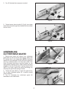
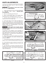
2. Thread set screw (B) Fig. 21 back into post (F) Fig.
20, to keep cutterhead guard (C) in position during
jointer operation.
3. Fig. 21, illustrates the cutterhead guard (C)
assembled to the infeed table.
Fig. 20
F
E
C
Fig. 21
B
C