


20
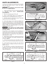
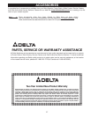
KNIVES MUST BE INSTALLED
CORRECTLY AS SHOWN IN FIG. 58.
8. The knives are adjusted correctly when the cutting
edge of the knife extends out .060” from the cutterhead
diameter.
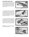
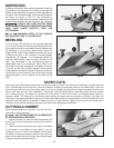
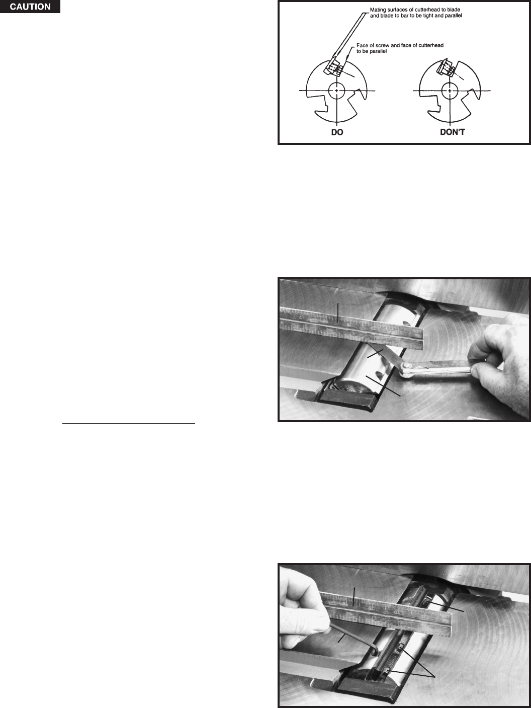
9. Carefully rotate the cutterhead (G) Fig. 59, until the
round portion of the cutterhead is on top as shown.
10. Place a .060” feeler gage (H) Fig. 59, on the
cutterhead and using a straight edge (J) on the rear table
adjust the height of the rear table until it is .060” above
the cuttinghead diameter, as shown.
11. Lock the rear table in position and remove the feeler
gage.
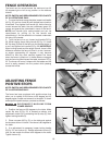
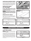
12. Lower the infeed table and place a straight edge (J)
Fig. 60, on the outfeed table extending over the
cutterhead as shown.
13. Rotate the cutterhead by hand until the knife is at its
highest point at each end of the cutterhead. To raise the
knife, use wrench (E) Fig. 60, and turn raising screw
clockwise until the knife just touches the straight edge
(J) on each end and center of the cutterhead when the
knife is at its highest point. When you are certain the
knife is adjusted properly, tighten the four locking
screws (B) by turning them counterclockwise.
14. Adjust the remaining two knives in the same manner.
MAKE CERTAIN THAT ALL KNIVES ARE SECURELY
FASTENED IN CUTTERHEAD BEFORE TURNING ON
POWER.
15. Replace cutterhead guard.
Fig. 58
Fig. 59
Fig. 60
J
H
G
E
J
B
B