


7
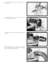
Fig. 7
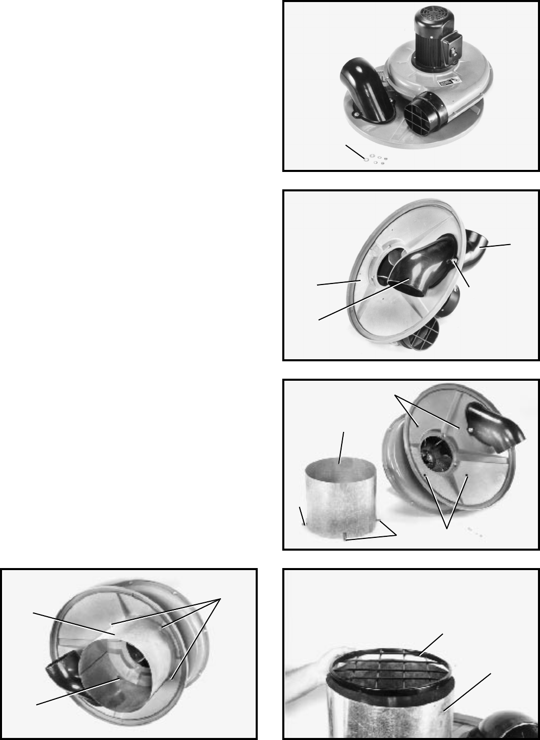
Fig. 8
Fig. 9
Fig. 11Fig. 10
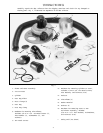
5. Position the remaining inlet elbow (K) Fig. 8, at the
underside of dust collector lid (C) as shown. Align the
mounting holes in inlet elbows (K) Fig. 8, with screws (J)
assembled to upper inlet elbow (H) shown in Fig. 7,
STEP 4, and fasten the upper and lower inlet elbows to
the cover with remaining two flat washers, lockwashers,
and locknuts (J) Figs. 7 and 8.
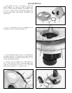
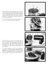
6. Place the sheet metal cylinder (L) Fig. 9, onto the
underside of the cover. Align four holes in cylinder brack -
et, three of which are shown at (M), with four holes (N) in
the underside of cover and fasten with four 1/4-20 x 5/8
hex head screws, lockwashers, and locknuts (P) Fig. 10.
NOTE: Assemble screws from the top of the lid down-
ward. CAUTION: Sheet metal cylinder (L) is extremely
sharp; use protective gloves when assembling the sheet
met al to the underside of the lid.
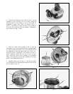
7. Assemble safety grid (V) Fig. 11, over metal cylinder
(L) and fasten grid to cylinder with three p an head screws
(W) as shown in Fig. 12.
C
K
J
H
N
N
M
M
L
L
P
P
L
V
J