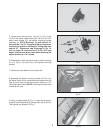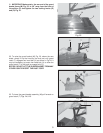
Fig. 11
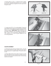
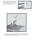
Fig. 12
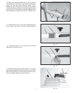
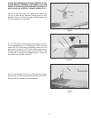
Fig. 13
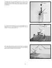
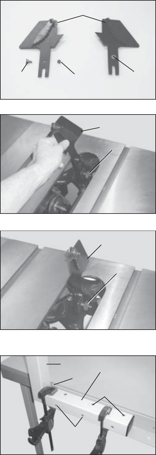
Fig. 14
6
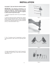
10. Insert index pin (T) Fig. 11, through the hole in splitter
(U), as shown, and fasten with locknut (V). Fig 11 illustrates
the index pin assembly arrangement for both right and left
tilting arbor saws.
11. Loosen knob (F) Fig. 12, and slide splitter (U) down as
far as possible into the splitter mounting bracket and tighten
knob (F). Fig 13 illustrates the splitter assembled to the
mounting bracket. IMPORTANT: When performing non
thru-cutting operations, such as dadoing, the splitter (U)
Figs. 12 and 13, can be removed by loosening knob (F).
This enables you to use the guard basket for non
thru-cutting operations.
GUARD ASSEMBLY
12. Clamp the guard mounting bracket (A) Fig. 14 to the
back rail (B) of the fence system, making sure the inside of
the vertical post (C), is approximately 1/4” past the end of
rail (B).
13. Using a 9/32” drill bit, drill six holes in the rear rail, three
each to be drilled into the horizontal and vertical portion of
the back rail (B), using the holes (D) and (E) in the mounting
bracket as a template.
T
T
U
V
A
B
C
D
E
F
U
U
F
LEFT-TILT
RIGHT-TILT


