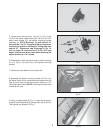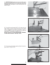
Fig. 19
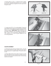
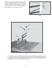
Fig. 20
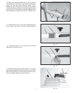
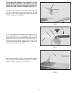
Fig. 21
8
18. Make certain the hood assembly (M) Fig. 19, is in line with
the basket body assembly (N). When you are certain hood
assembly (M) is in line with basket body assembly (M), tighten
4 screws (P).
19. Thread locking knobs (R) Fig. 20, into threaded nut on
adjusting arm (J). Insert basket body assembly (N) Fig. 20
into the “T” of the adjusting arm (J).
20. Loosen the two locking knobs (R) & (H) Fig. 21, and adjust
T-arm (J) and blade guard basket assembly (N) until the guard
basket (M) is centered over the saw blade.
M
N
P
J
N
R
R
H
J
N
M


