


English
7
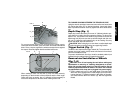
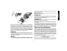
For more accurate square cuts, disconnect the power supply,
loosen the two fence bolts, push arm down until wheel extends into
base. Place a square against the wheel and adjust fence against
the square. Securely tighten both fence bolts before use.
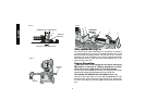
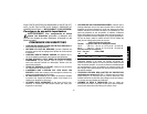
When making a miter cut, the vise (F) may not clamp securely,
depending on the thickness of the workpiece and the miter angle.
Other aids (such as spring, bar or C-clamps) will be necessary to
secure the workpiece to the fence when making these cuts.
J
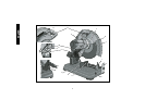
FIG. 6
E
Q
R
FIG. 5
Q
E
G
F
R
TO CHANGE SPACING BETWEEN THE FENCE AND VISE
Using the wrench provided, loosen and remove the two fence bolts
(Q). Adjust the fence (E) to desired locations. Insert both fence
bolts in provided locations. Securely tighten both fence bolts before
use.
Depth Stop (Fig. 1)
Depth stop is set at the factory for a new 14" (355mm) wheel to pre-
vent wheel from cutting into the supporting surface. To allow more
depth of cut, use the 8mm hex wrench (G) provided to loosen the
depth stop bolt (M) and raise bolt to desired height and then turn
jam nut (P) clockwise until seated firmly on the casting. Securely
tighten the depth stop bolt before use.
CAUTION: When changing to a new wheel, readjust depth stop
to original position to prevent cutting into supporting surface.
Trigger Switch (Fig. 1)
To start the tool, depress the trigger switch (N). To turn the tool off,
release the trigger switch. Keep hands and material from wheel
until it has coasted to a stop.
To prevent unauthorized use of tool, install a standard padlock (not
included) into the padlock hole (O) located in the trigger.
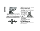
Removal and Installation of Wheels
(Fig. 7, 8)
CAUTION: Turn off and unplug the tool before making any
adjustments or removing or installing attachments or acces-
sories. Be sure the trigger switch is in the OFF position. Do not
make any adjustment while the wheel is in motion. Do not make
any adjustment while chop saw is plugged into power supply.
1. Push in wheel lock lever (L) and rotate wheel (J) by hand until
wheel lock lever engages slot in inside flange (S) to lock wheel.
Loosen the bolt (T) counterclockwise in the center of the abra-
sive wheel with the 8mm hex wrench (G). Bolt has right-hand
thread.