


• DO NOT attempt to charge the battery pack with any chargers other than the ones in
this manual.
The charger and battery pack are specifically designed to work together.
•
These chargers are not intended for any uses other than charging DEWALT recharge-
able batteries.
Any other uses may result in risk of fire, electric shock or electrocution.
•
Do not expose charger to rain or snow.
• Pull by plug rather than cord when disconnecting charger. This will reduce risk of
damage to electric plug and cord.
•
Make sure that cord is located so that it will not be stepped on, tripped over, or
otherwise subjected to damage or stress.
• Do not use an extension cord unless it is absolutely necessary. Use of improper
extension cord could result in risk of fire, electric shock, or electrocution.
•
An extension cord must have adequate wire size (AWG or American Wire Gauge) for
safety.
The smaller the gauge number of the wire, the greater the capacity of the cable, that
is 16 gauge has more capacity than 18 gauge. When using more than one extension to
make up the total length, be sure each individual extension contains at least the minimum
wire size.
•
Do not place any object on top of charger or place the charger on a soft surface that
might block the ventilation slots and result in excessive internal heat.
Place the
charger in a position away from any heat source. The charger is ventilated through slots in
the top and the bottom of the housing.
•
Do not operate charger with damaged cord or plug — have them replaced immediately.
•
Do not operate charger if it has received a sharp blow, been dropped, or otherwise
damaged in any way.
Take it to an authorized service center.
•
Do not disassemble charger; take it to an authorized service center when service or
repair is required.
Incorrect reassembly may result in a risk of electric shock, electrocution
or fire.
•
Disconnect the charger from the outlet before attempting any cleaning. This will
reduce the risk of electric shock.
Removing the battery pack will not reduce this risk.
•
NEVER attempt to connect 2 chargers together.
•
The charger is designed to operate on standard household electrical power
(120 Volts). Do not attempt to use it on any other voltage.
This does not apply to the
vehicular charger
.
SAVE THESE INSTRUCTIONS
FOR FUTURE USE
Chargers
Your tool uses a DEWALT charger. Your battery can be charged in DEWALT 1 Hour Chargers,
15 Minute Chargers or Vehicular 12 Volt Charger. Be sure to read all safety instructions before
using your charger. Consult the chart on the back cover of this manual for compatibility of
chargers and battery packs.
Charging Procedure
DANGER: Electrocution hazard.
120 volts are present at charging terminals. Do not probe
with conductive objects. Electric shock or electrocution may result.
1. Plug the charger into an appropriate outlet.
2.
Insert the battery pack into the charger. The red (charging) light will blink continuously
indicating that the charging process has started.
3. The completion of charge will be indicated by the red light remaining ON continuously. The
pack is fully charged and may be used at this time or left in the charger
.
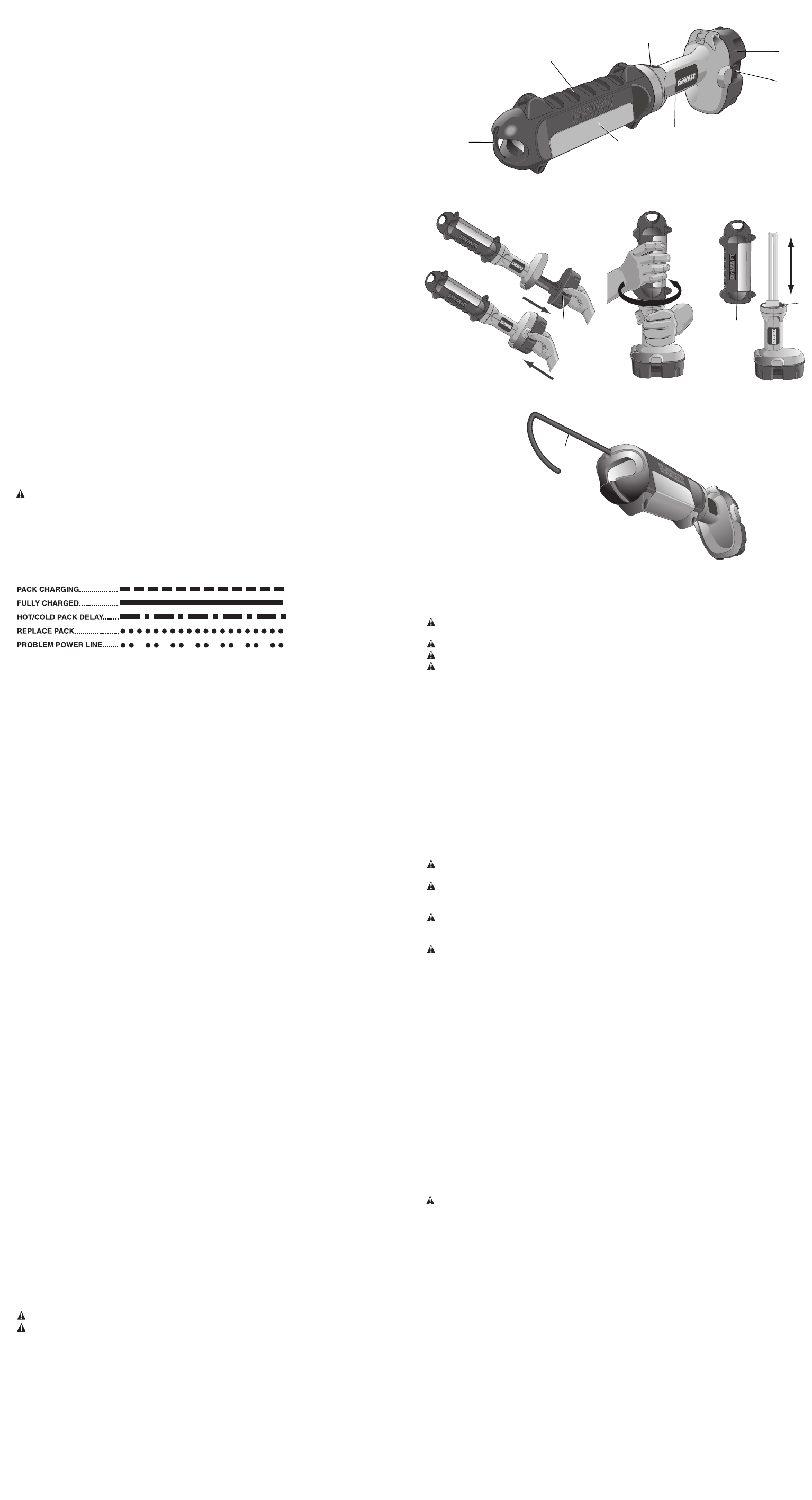
Indicator Light Operation
Charge Indicators
Some chargers are designed to detect certain problems that can arise with battery packs.
Problems are indicated by the red light flashing at a fast rate. If this occurs, re-insert battery
pack into the charger. If the problem persists, try a different battery pack to determine if the
charger is OK. If the new pack charges correctly
, then the original pack is defective and
should be returned to a service center or other collection site for recycling. If the new bat
-
tery pack elicits the same trouble indication as the original, have the charger tested at an
authorized service center
.
HOT/COLD PACK DELAY
Some chargers have a Hot/Cold Pack Delay feature: when the charger detects a battery that
is hot, it automatically starts a Hot Pack Delay
, suspending charging until the battery has
cooled.
After the battery has cooled, the charger automatically switches to the Pack Charging
mode. This feature ensures maximum battery life. The red light flashes long, then short while
in the Hot Pack Delay mode.
PROBLEM POWER LINE
Some chargers have a Problem Power Line indicator. When the charger is used with some
portable power sources such as generators or sources that convert DC to
AC, the charger may
temporarily suspend operation,
flashing the red light with two fast blinks followed by a
pause
.
This indicates the power source is out of limits.
LEAVING THE BATTERY PACK IN THE CHARGER
The charger and battery pack can be left connected with the red light glowing indefinitely. The
charger will keep the battery pack fresh and fully charged.
NOTE: A
battery pack will slowly lose its charge when kept out of the charger
. If the battery
pack has not been kept on maintenance charge,
it may need to be recharged before use.
A
battery pack may also slow
ly lose its charge if left in a charger that is not plugged into an
appropriate AC source.
WEAK BATTERY PACKS: Chargers can also detect a weak battery. Such batteries are still
usable but should not be expected to perform as much work. In such cases, about 10 seconds
after battery insertion, the charger will beep rapidly 8 times to indicate a weak battery condi-
tion.
The charger will then go on to charge the battery to the highest capacity possible.
Important Charging Notes
1. Longest life and best performance can be obtained if the battery pack is charged when the
air temperature is between 65
°
F and 75°F (18°- 24°C). DO NOT charge the battery pack
in an air temperature below +40°F (+4.5°C), or above +105°F (+40.5°C). This is important
and will prevent serious damage to the battery pack.
2. The charger and battery pack may become warm to touch while charging. This is a nor-
mal condition, and does not indicate a problem. To facilitate the cooling of the battery pack
after use, avoid placing the charger or battery pack in a warm environment such as in a
metal shed, or an uninsulated trailer.
3.
If the battery pack does not charge properly:
a. Check current at receptacle by plugging in a lamp or other appliance
b.
Check to see if receptacle is connected to a light switch which turns power of
f when you
turn out the lights.
c. Move charger and battery pack to a location where the surrounding air temperature is
approximately 65°F - 75°F (18°- 24°C).
d. If charging problems persist, take the tool, battery pack and charger to your local
service center
.
4. The battery pack should be recharged when it fails to produce sufficient power on jobs
which were easily done previously
. DO NOT
CONTINUE to use under these conditions.
Follow the charging procedure. You may also charge a partially used pack whenever you
desire with no adverse af
fect on the battery pack.
5. Under certain conditions, with the charger plugged into the power supply, the exposed
charging contacts inside the charger can be shorted by foreign material. Foreign materials
of a conductive nature such as, but not limited to, steel wool, aluminum foil, or any buildup
of metallic particles should be kept away from charger cavities. Always unplug the charg-
er from the power supply when there is no battery pack in the cavity
. Unplug charger before
attempting to clean.
6. Do not freeze or immerse charger in water or any other liquid.
WARNING: Don’t allow any liquid to get inside charger. Electric shock may result.
CAUTION: Never attempt to open the battery pack for any reason. If the plastic housing of
the battery pack breaks or cracks, return to a service center for recycling.
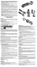
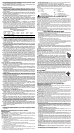
Components (Fig. 1)
A.
Battery pack
E. Base
B. Release buttons F. Lens
C.
Switch
G.
Hook
D. Lens cover assembly
OPERA
TION
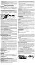
Installing and Removing the Battery Pack (Fig. 2)
NOTE: Make sure your battery pack is fully charged.
To insert the battery pack (A) into your fluorescent area light, slide it into the end of the light
until it snaps into place.
T
o remove the battery pack
, depress the release buttons (B) and
withdraw the battery pack.
FIG. 1
FIG. 2
FIG. 5
FIG. 4
Switch (Fig. 1)
To turn the light on, slide the switch (C) forward. To turn it off, slide the switch back.
Replacing the Fluorescent Tube (Fig. 3, 4)
CAUTION: Disconnect battery pack from tool before replacing the fluorescent tube.
Such preventative safety measures reduce the risk of personal injury.
CAUTION: Burn hazard. Lens or fluorescent tube may be hot immediately after use.
CAUTION: V
ision may be impaired when looking directly into fluorescent light.
CAUTION: If replacing a broken tube, protect your hands before attempting to remove the
tube. Do not remove any pieces of broken glass or tube from the socket area with bare hands,
or personal injury may occur
.
NOTE: Use only DEWALT DC5273 13W tube.
1. With one hand on the lens cover assembly (D) and the other hand on the base (E), slowly
rotate the cover counterclockwise from its original position.
2.
Carefully lift the lens cover assembly up and over the tube. Set aside.
3. Carefully remove the tube from the socket by gently pulling up from the base. Check
to ensure the socket and the area around the socket is free of dirt, dust and other
contaminants.
NOTE: A
clear, rubber end cap is mounted inside the top portion of the lens cover
assembly
This endcap must align with the top of the fluorescent tube in order for the
lens
cover assembly to fit properly onto the handle.
The rubber end cap should be in the
correct position when lens cover assembly is removed to allow new tube to fit.
4.
Once the new tube is in place, align the slots (H) at the bottom of the lens cover assembly
with the slots (I) at the top of the base.
5. Push the lens cover assembly down then rotate it clockwise to lock into place.
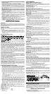
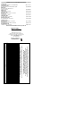
Hook (Fig. 5)
CAUTION: When hook is in use, do not shake light. Personal injury or property damage may
occur
.
CAUTION: When light is hung by the hook, do not shake the light or object that it is hanging
from. Do not hang the light from any electrical wires or anything that it is not secure. Personal
injury or property damage may occur
.
CAUTION: Only use the hook for hanging the area light. The hook is not intended to
support additional weight. Do not attach or hang anything additional to the light or risk of
breakage may occur
.
CAUTION: Do not reach with the hook or use the hook to support your weight in any
situation.
The built-in hook (G) telescopes out of the lens cover assembly (D).
This hook locks into place
in the down position and when fully extended, as shown in Figure 5. The hook rotates
360 degrees and can be locked at 45-degree positions when fully extended.
MAINTENANCE
• MAINTAIN TOOL WITH CARE. Keep fluorescent tube area clean for best and safest
performance.
• Do not attempt to repair the area light. To assure product safety and reliability, repairs,
maintenance, and adjustments should be performed by authorized D
EWALT service
centers.
Cleaning
Use only mild soap and a damp cloth to clean the tool. Many household cleaners contain
chemicals which could seriously damage plastic. Also, do not use gasoline, turpentine,
lacquer or paint thinner, dry cleaning fluids or similar products. Never let any liquid get
inside the tool; never immerse any part of the tool into a liquid.
Accessories
A replacement fluorescent tube is available at extra cost at your local DEWALT service center.
Recommended accessories for use with your tool are available at extra cost from your local
dealer or authorized service center
. If you need assistance in locating any accessory for your
tool, please contact D
EWALT Industrial Tool Co., 701 East Joppa Road, Baltimore, MD 21286,
call 1-800-4-D
EWALT (1-800-433-9258) or visit our website www.dewalt.com.
CAUTION: The use of any other accessory not recommended for use with this fluorescent
light could be hazardous.
Repairs
To assure product SAFETY and RELIABILITY, repairs, maintenance and adjustment (including
brush inspection and replacement) should be performed by a D
EWALT factory service center,
a D
EW
AL
T
authorized service center or other qualified service personnel.
Always use identical
replacement parts.
Three Year Limited Warranty
DEWALT will repair, without charge, any defects due to faulty materials or workmanship for
three years from the date of purchase. This warranty does not cover part failure due to normal
wear or tool abuse. For further detail of warranty coverage and warranty repair information,
visit www.dewalt.com or call 1-800-4-D
EWALT (1-800-433-9258). This warranty does not apply
to accessories or damage caused where repairs have been made or attempted by others. This
warranty gives you specific legal rights and you may have other rights which vary in certain
states or provinces.
In addition to the warranty, D
EWALT tools are covered by our:
1 YEAR FREE SERVICE
DEWALT will maintain the tool and replace worn parts caused by normal use, for free, any time
during the first year after purchase.
90 DAY MONEY BACK GUARANTEE
If you are not completely satisfied with the performance of your DEWALT Power Tool, Laser,
or Nailer for any reason, you can return it within 90 days from the date of purchase with a
receipt for a full refund – no questions asked.
RECONDITIONED PRODUCT: Reconditioned product is covered under the 1 Year Free
Service Warranty. The 90 Day Money Back Guarantee and the Three Year Limited Warranty
do not apply to reconditioned product.
FIG. 5
E
F
A
B
H
I
B
C
D
G
G