


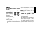

Side handle (H) clamps to the front of the gear case and may be rotated
360˚ to permit right- or left-hand use. Side handle must be tightened
sufficiently to resist the twisting action of the tool if the accessory binds
or stalls. Be sure to grip the side handle at the far end to control the tool
during a stall.
If model is not equipped with side handle, grip drill with one hand on
the handle and one hand on the battery pack.
NOTE: Side handle comes equipped on models DCD940, DCD950,
DCD960 and DCD970.
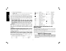
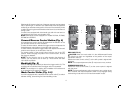
Forward/Reverse Control Button (Fig. 2)
A forward/reverse control button (B) determines the direction of the
tool and also serves as a lock off button.
To select forward rotation, release the trigger switch and depress the
for ward/re verse control button on the right side of the tool.
To select reverse, release the trigger switch and depress the forward/
reverse control button on the left side of the tool.
The center position of the control button locks the tool in the OFF
position. When changing the position of the control button, be sure
the trigger is released.
NOTE: The first time the tool is run after changing the direction of
rotation, you may hear a click on start up. This is normal and does
not indicate a problem.
Worklight (Fig. 2)
There is a worklight (C) located just above the trigger switch (A). The
worklight will be activated when the trigger switch is squeezed.
NOTE: The worklight is for lighting the immediate work surface and
is not intended to be used as a flashlight.
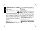
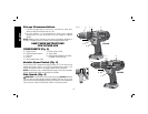
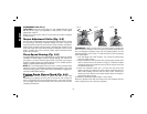
Mode Control Collar (Fig. 3–5)
Your drill is equipped with a separate mode control collar (F) to switch
between drilling, screwdriving and hammerdrilling mode.
FIG. 3
E
F
G
SCREWDRIVING
DRILLING
HAMMERDRILLING
E
F
G
FIG. 5
FIG. 4
DRILLING (FIG. 3)
CAUTION: When the mode collar is in the drill/hammerdrill mode,
the drill will not clutch out regardless of the position of the torque
adjustment collar (E).
Rotate the mode control collar (F) so the drill symbol is aligned with
the arrow.
NOTE: The torque adjustment collar (E) may be set on any number.
SCREWDRIVING (FIG. 4)
Rotate the mode control collar (F) so the screw symbol is aligned
with the arrow.
NOTE: The torque adjustment collar may be set to any number at any
time. However, the torque adjustment collar is only engaged during
screwdriving mode and not in drill and hammerdrill modes.
English
11