


knob and tilt shoe to the desired angle by aligning the pointer with the desired angle mark.
Retighten knob firmly (clockwise).
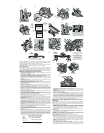
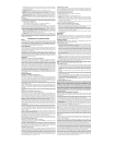
KERF INDICATOR (FIG. 8)
The front of the saw shoe has a kerf indicator (L) for vertical and bevel cutting. This indicator
enables you to guide the saw along cutting lines penciled on the material being cut. The indicator
lines up with the left (inner) side of the saw blade, which makes the slot or “kerf” cut by the moving
blade fall to the right of the indicator. Guide along the penciled cutting line so that the kerf falls into
the waste or surplus material. Figure 8 shows the dimensions of the shoe. Note that the left side
is 5 1/2” between the left side of the blade and the left edge of the shoe (standard 6x lumber). The
right dimension is 1 1/2” (standard 2x lumber).
SHOE ALIGNMENT
Your saw has been set at the factory for accurate vertical cuts (a 90 degree angle between the
bottom of the shoe (M) and the blade). The edge of the shoe has also been set parallel to the blade
so that it will not bind when using an edge guide. If the saw should ever need adjustment, it may
be done as follows:
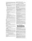
ADJUSTING FOR 90° CUTS (FIG. 9-11)
1. DISCONNECT PLUG FROM POWER SUPPLY.
2. Adjust the saw to 0° bevel.
3. Place saw on blade side (Figure 9). Retract blade guard.
4. Loosen quadrant knob. Place a square against the blade and shoe to adjust the 90° setting.
5. Loosen the hex nut (N) and move the adjustment screw (O) so that the shoe will stop at the
proper angle as shown in Figure 11. Lock the screw in place by tightening the hex nut.
6. It may be necessary to adjust the quadrant angle pointer to line up on “O” after shoe has
been adjusted.
ADJUSTING THE SHOE PARALLEL TO THE BLADE
1. DISCONNECT PLUG FROM POWER SUPPLY.
2. Loosen the hex nut (N) shown in Figure 10 and then turn the adjustment screw (O) in or
out as needed to adjust for parallelism.
3. Adjust the shoe until it is parallel to the blade by measuring from the edge of the shoe to the
blade, front & rear. You can measure from the outside edge of the blade to the shoe as
shown in Figure 8 or from the inner edge of the blade to the wider part of the shoe. (Do not
measure from the tips of any saw blade teeth.)
4. When the shoe and blade are parallel, hold the adjusting screw in place and tighten the hex
nut firmly.
OPERATION
Switch
Pull the trigger switch to turn the motor “ON”. Releasing the trigger turns the motor “OFF”.
Releasing the trigger also automatically actuates the electric brake. This tool has no provision
to lock the switch in the “ON” position, and should never be locked “ON” by any other means.
Changing Blades
CAUTION: ALWAYS TURN OFFAND DISCONNECT TOOL BEFORE CHANGING ACCES-
SORIES OR MAKING ANY ADJUSTMENTS.
TO INSTALL THE BLADE
1. Place inner clamp washer (D) on saw spindle with the large flat surface facing out toward
the blade (Fig. 2).
2. Retract the lower blade guard (C) and place blade on saw spindle against the inner clamp
washer, making sure that the blade will rotate in the proper direction (the direction of the rota-
tion arrow on the saw blade and the teeth must point in the same direction as the direction of
rotation arrow on the saw). Do not assume that the printing on the blade will always be fac-
ing you when properly installed. When retracting the lower blade guard to install the blade,
check the condition and operation of the lower blade guard to assure that it is working prop-
erly. Make sure it moves freely and does not touch the blade or any other part, in all angles
and depths of cut.
3. Place outer clamp washer (F) on saw spindle with the large flat surface against the blade and
the wording on the outer clamp washer facing you.
4. Thread blade clamping screw (G) into saw spindle by hand (screw has right-hand threads
and must be turned clockwise to tighten).
5. Depress the blade lock (B) while turning the saw spindle with the blade wrench until the
blade lock engages and the blade stops rotating (Fig. 3).
6. Tighten the blade clamping screw firmly with the blade wrench.
NOTE: Never engage the blade lock while saw is running, or engage in an effort to stop the tool.
Never turn the saw on while the blade lock is engaged. Serious damage to your saw will result.
TO REPLACE THE BLADE
1. To loosen the blade clamping screw (G), depress the blade lock (B) and turn the saw spin-
dle with the blade wrench until the blade lock engages and the blade stops rotating. With
the blade lock engaged, turn the blade clamping screw clockwise with the blade wrench
(screw has right-hand threads and must be turned counterclockwise to loosen).
2. Remove the blade clamping screw (G) and outer clamp washer ( F) only. Remove old blade.
3. Clean any sawdust that may have accumulated in the guard or clamp washer area and check
the condition and operation of the lower blade guard as previously outlined. Do not lubricate
this area.
4. Select the proper blade for the application (see Blades). Always use blades that are the cor-
rect size (diameter) with the proper size and shape center hole for mounting on the saw
spindle. Always assure that the maximum recommended speed (rpm) on the saw blade
meets or exceeds the speed (rpm) of the saw.
5. Follow steps 2 through 6 under To Install the Blade, making sure that the blade will rotate
in the proper direction.
LOWER BLADE GUARD
WARNING: The lower blade guard is a safety feature which reduces the risk of serious
personal injury. Never use the saw if the lower guard is missing, damaged, misassembled
or not working properly. Do not rely on the lower blade guard to protect you under all cir-
cumstances. Your safety depends on following all warnings and precautions as well as
proper operation of the saw. Check lower guard for proper closing before each use as
outlined in Additional Safety Rules for Circular Saws. If the lower blade guard is missing
or not working properly, have the saw serviced before using. To assure product safety
and reliability, repair, maintenance and adjustment should be performed by an author-
ized service center or other qualified service organization, always using identical
replacement parts.
Workpiece Support
Figure 12 shows proper sawing position. Note that hands are kept away from cutting area, and
power cord is positioned clear of the cutting area so that it will not get caught or hung up on the
work.
To avoid kickback, DO support board or panel NEAR the cut and on both sides of the cut,
(Figure 13). DON’T support board or panel away from the cut, (Figure 14). When ripping long
narrow strips, support cut-off waste material.
When operating the saw, keep the cord away from the cutting area and prevent it from becom-
ing hung up on the work piece. Note that a special Cord Keeper has been provided on the tool’s
handle. Simply press the cord into the keeper to keep it in sight and out of the way.
WARNING: It is important to support the work properly and to hold the saw firmly to prevent
loss of control which could cause personal injury; Figure 12 illustrates typical hand support of the
saw.
ALWAYS DISCONNECT SAW BEFORE MAKING ANYADJUSTMENTS! Place the work with its
“good” side - the one on which appearance is most important - down. The saw cuts upward, so
any splintering will be on the work face that is up when you saw it.
Support the work so that the cut will be on your right. Place the wider portion of the saw shoe
on that part of the work piece which is solidly supported, not on the section that will fall off when
the cut is made. As examples, Figure15 illustrates the RIGHT way to cut off the end of a board,
and Figure 16 the WRONG way. Always clamp work. Don’t try to hold short pieces by hand!
Remember to support cantilevered and overhanging material. Use caution when sawing mate-
rial from below.
CUTTING
Be sure saw is up to full speed before blade contacts material to be cut. Starting saw with blade
against material to be cut or pushed forward into kerf can result in kickback.
Push the saw forward at a speed which allows the blade to cut without laboring. Hardness and
toughness can vary even in the same piece of material, and knotty or damp sections can put a
heavy load on the saw. When this happens, push the saw more slowly, but hard enough to keep
it working without much decrease in speed. Forcing the saw can cause rough cuts, inaccuracy,
kickback and over-heating of the motor.
Should your cut begin to go off the line, don’t try to force it back on. Release the switch and allow
blade to come to a complete stop. Then you can withdraw the saw, sight anew, and start a new
cut slightly inside the wrong one. In any event, withdraw the saw if you must shift the cut. Forcing
a correction inside the cut can stall the saw and lead to kickback. IF SAW STALLS, RELEASE
THE TRIGGER AND BACK THE SAW UNTIL IT IS LOOSE. BE SURE BLADE IS STRAIGHT
IN THE CUT AND CLEAR OF THE CUTTING EDGE BEFORE RESTARTING.
As you finish a cut, release the trigger and allow the blade to stop before lifting the saw from the
work. As you lift the saw, the spring-tensioned telescoping guard will automatically close under
the blade. Remember the blade is exposed until this occurs, never reach under the work for any
reason whatsoever. When you have to retract the telescoping guard manually (as is necessary
for starting pocket cuts) always use the retracting lever.
NOTE: When cutting thin strips, be careful to ensure that small cutoff pieces don’t hang up on
inside of lower guard.
Always use a fence or straight edge guide when ripping.
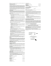
POCKET CUTTING (FIG. 17)
DISCONNECT PLUG FROM POWER SUPPLY. Adjust saw shoe so blade cuts at desired
depth. Tilt saw forward and rest front of the shoe on material to be cut. Using the retracting lever,
retract blade guard to an upward position. Lower rear of shoe until blade teeth almost touch cut-
ting line. Now release the blade guard and its contact with the work will keep it in position to
open freely as you start the cut. Start the motor and gradually lower the saw until its shoe rests
flat on the material to be cut. Advance saw along the cutting line until cut is completed. Release
trigger and allow blade to stop completely before withdrawing the blade from the material. When
starting each new cut, repeat as above. Never tie the blade guard in a raised position.
Kickback
When the saw blade becomes pinched or twisted in the cut, kickback can occur. The saw is
thrust rapidly back toward the operator. When the blade is pinched or bound tightly by the kerf
closing down, the blade stalls and the motor reaction drives the unit backward. When the blade
becomes twisted or misaligned in the cut, the teeth at the back edge of the blade can dig into
the top surface of the wood causing the blade to climb out of the kerf and jump back toward the
operator.
Kickback is more likely to occur when any of the following conditions exist.
1. IMPROPER WORKPIECE SUPPORT
A.Sagging or improper lifting of the cut off piece causing pinching of the blade.
B.Cutting through material supported at the outer ends only (see Figure 14). As the materi-
al weakens it sags, closing down the kerf and pinching the blade.
C.Cutting of a cantilevered or overhanging piece of material from the bottom up in a verti-
cal direction. The falling cut off piece can pinch the blade.
D.Cutting off long narrow strips (as in ripping). The cut off strip can sag or twist closing the
kerf and pinching the blade.
E.Snagging the lower guard on a surface below the material being cut momentarily reduc-
ing operator control. The saw can lift partially out of the cut increasing the chance of blade
twist.
2. IMPROPER DEPTH OF CUT SETTING ON SAW
Using the saw with an excessive depth of cut setting increases loading on the unit and sus-
ceptibility to twisting of the blade in the kerf. It also increases the surface area of the blade
avaliable for pinching under conditions of kerf close down.
3. BLADE TWISTING (MISALIGNMENT IN CUT)
A.Pushing harder to cut through a knot, a nail, or a hard grain area can cause the blade to
twist.
B.Trying to turn the saw in the cut (trying to get back on the marked line) can cause blade
twist.
C.Extended reach or operating saw with poor body control (out of balance), can result in
twisting the blade.
D.Changing hand grip or body position while cutting can result in blade twist.
E.Backing unit up to clear blade can lead to twist if not done carefully.
4. Materials that require extra attention
A.Wet lumber
B.Green lumber (material freshly cut or not kiln dried)
C.Pressure treated lumber (material treated with preservatives or anti-rot chemicals)
5. USE OF DULL OR DIRTY BLADES
Dull or dirty blades cause increased loading of the saw. To compensate, an operator will
usually push harder which further loads the unit and promotes twisting of the blade in the
kerf. Worn blades may also have reduced body clearance which increases the chance of
binding and increased loading.
6. LIFTING THE SAW WHEN MAKING BEVEL CUTS
Bevel cuts require special operator attention to proper cutting techniques - especially guid-
ance of the saw. Both blade angle to the shoe and greater blade surface in the material
increase the chance for binding and misalignment (twist) to occur.
7. RESTARTING A CUT WITH THE BLADE TEETH JAMMED AGAINST THE MATERIAL
The saw should be brought up to full operating speed before starting a cut or restarting a
cut after the unit has been stopped with the blade in the kerf. Failure to do so can cause
stalling and kickback.
Any other conditions which could result in pinching, binding, twisting, or misalignment of the
blade could cause kickback. Refer to the sections on “Adjustments And Set-Up” and
“Operation” for procedures and techniques that will minimize the occurrence of kickback.
Blades
A dull blade will cause slow, inefficient cutting overload on the saw motor, excessive splintering
and could increase the possibility of kickback. It is a good practice to keep extra blades on hand
so that sharp blades are available while the dull ones are being sharpened (See “SAWS-
SHARPENING” in the Yellow Pages). In fact, many lower priced blades can be replaced with
new ones at very little cost over the sharpening price.
Hardened gum on the blade will slow down the cutting. This gum can best be removed with
kerosene, turpentine or oven cleaner.
D
EWALT manufactures a complete line of saw blades and the following types of blades are
available from your service center.
VISUALLY EXAMINE CARBIDE BLADES BEFORE USE. REPLACE IF DAMAGED.
Cleaning and Lubrication
Use only mild soap and a damp cloth to clean the tool. Never let any liquid get inside the tool;
never immerse any part of the tool into a liquid.
Self lubricating ball and roller bearings are used in the tool and relubrication is not required.
However, it is recommended that, once a year, you take or send the tool to a service center for
a thorough cleaning, inspection and lubrication of the gear case.
Accessories
Recommended accessories for use with your tool are available at extra cost from your distribu-
tor or local service center.
If you need assistance in locating any accessory, please contact DEWALT Industrial Tool Co.,
701 East Joppa Road, Baltimore, MD 21286 or call 1-800-4-D
EWALT (1-800-433-9258).
A. RIP FENCE - attaches to top of saw shoe; permits rip cuts without penciled guide line.
B. SAW PROTRACTOR - guides saw for accurate cut-off work; adjusts from 0 to 70 degrees.
C. CUT-OFF GUIDE - for 90 degree or 45 degree cuts.
CAUTION: The use of any non-recommended accessory may be hazardous.
Repairs
To assure product SAFETY and RELIABILITY, repairs, maintenance and adjustment (including
brush inspection and replacement) should be performed by authorized service centers or other
qualified service organizations, always using identical replacement parts.
Three Year Limited Warranty
DEWALT will repair, without charge, any defects due to faulty materials or workmanship for three
years from the date of purchase. This warranty does not cover part failure due to normal wear
or tool abuse. For further detail of warranty coverage and warranty repair information, visit
www.dewalt.com or call 1-800-4-D
EWALT (1-800-433-9258). This warranty does not apply to
accessories or damage caused where repairs have been made or attempted by others. This
warranty gives you specific legal rights and you may have other rights which vary in certain
states or provinces.
In addition to the warranty, D
EWALT tools are covered by our:
1 YEAR FREE SERVICE
D
EWALT will maintain the tool and replace worn parts caused by normal use, for free, any time
during the first year after purchase.
90 DAY MONEY BACK GUARANTEE
If you are not completely satisfied with the performance of your D
EWALT Power Tool, Laser, or
Nailer for any reason, you can return it within 90 days from the date of purchase with a receipt
for a full refund – no questions asked.
RECONDITIONED PRODUCT: Reconditioned product is covered under the 1 Year Free
Service Warranty. The 90 Day Money Back Guarantee and the Three Year Limited Warranty do
not apply to reconditioned product.
FREE WARNING LABEL REPLACEMENT: If your warning labels become illegible or are miss-
ing, call 1-800-4-DEWALT for a free replacement.
POUR TOUT RENSEIGNEMENT SUPPLÉMENTAIRE SUR CET OUTIL OU TOUT AUTRE
OUTIL D
EWALT, COMPOSER SANS FRAIS LE NUMÉRO: 1 800 4-DEWALT (1 800 433-
9258)
Importantes mesures de sécurité
AVERTISSEMENT : Afin de réduire les risques d’incendie, de secousses électriques ou de
blessures lorsqu’on utilise des outils électriques, il faut toujours respecter les mesures de sécu-
rité suivantes.
LIRE TOUTES LES DIRECTIVES
Double isolation
Les outils à double isolation comportent deux couches distinctes d’isolant électrique ou une
double épaisseur d’isolant qui protègent l’utilisateur contre les risques de blessures provenant
du système électrique de l’outil. Ce système de double isolation élimine le besoin de mettre les
outils à la terre. En effet, l’outil est muni d’une fiche à deux broches, ce qui permet d’utiliser une
rallonge ordinaire sans avoir à se soucier d’assurer la mise à la terre.