


4
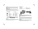
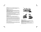
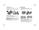
Components (Fig. 1)
A. Trigger switch E. Shoe
B. Lock-on button F. Rabbet fence (not shown)
C. Depth adjustment knob/front handle G. Rabbet fence adjustment knob
D. Switch Handle H. Chip discharge chute
C
FIG. 1
B
A
G
E
D
H
G
OPERATION
WARNING: To reduce the risk of serious personal injury, turn tool off and
disconnect tool from power source before making any adjustments or removing/
installing attachments or accessories.
Motor
Be sure your power supply agrees with the nameplate markings. 230 volts AC means
your tool may be operated only with alternating current and never with direct current.
Voltage decrease of more than 10% will cause loss of power and overheating. All
DEWALT tools are factory tested; if this tool does not operate, check the power supply.
Switch (Fig. 1)
CAUTION: Check that the tool is not ON before connecting it to a power supply. If
the trigger switch is ON when the tool is connected to the power supply, it will start
immediately. Damage to your tool or personal injury may result.
WARNING: Use of this tool can generate and/or disburse dust, which may cause
serious and permanent respiratory or other injury. Always use AS/NZS standard
approved respiratory protection appropriate for the dust exposure. Direct particles
away from face and body.
WARNING: We recommend the use of a residual current device with a residual
current rating of 30mA or less.
CAUTION: Wear appropriate personal hearing protection during use. Under some
conditions and duration of use, noise from this product may contribute to hearing
loss.
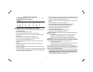
• The label on your tool may include the following symbols. The symbols and their
definitions are as follows:
V ..................volts A ..............amperes
Hz ................hertz W .............watts
min ..............minutes ..........alternating current
.........direct current ..........alternating or direct current
...............Class I Construction
n
o .............no load speed
....................(grounded) ............earthing terminal
...............Class II Constr uction ............safety alert symbol
....................(double insulated) BPM .........beats per minute
…/min .........per minute RPM .........revolutions per minute
sfpm ............surface feet per minute
SAVE ALL WARNINGS AND INSTRUCTIONS FOR
FUTURE REFERENCE
Introduction
Examine Figure 1 and your planer for a few minutes to become familiar with the various
features and the names used to describe them. The following sections will discuss the
various controls and you will need to know where they are.