


7
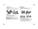
d. Simultaneously push the blade carrier (L) and the guide bar (M) into the
gauge plate inside wall (O), making sure that the carbide blade (I) is held
firmly against the gauge plate inside wall (O) and securely tighten the two hex
screws (P).
3. To Reinstall Blade
a. Remove the adjusted blade carrier/guide bar assembly from the gauge plate (N)
and place the heel of the guide bar (M) into the groove on the drum (Q).
b. Place the drum cover (K) over the blade carrier/guide bar assembly. Loosely
screw the three hex screws (J) into the drum (Q) so that there is a small gap
between the drum and the blade carrier (L).
c. Slide the carbide blade between the drum (Q) and the blade carrier (L) so that
the rib on the blade carrier sets into the groove in the blade.
d. Center the carbide blade (I) under the blade carrier (L) making sure the blade is
clear of the tool housing on both sides.
e. Securely tighten the three hex screws (J) to the drum.
4. Repeat procedure for the other blade.
High-speed Steel Blades
1. To Remove Blade from Planer
a. Loosen and remove the three hex head screws (J) with the 5 mm hex wrench
provided. Remove the drum cover (K) from the drum (Q).
b. Cautiously remove the guide bar/high speed steel blade assembly.
2. To Adjust Blade Using Gauge Plate (provided with tool)
a. Place the guide bar/high speed steel blade assembly on the gauge plate (N)
with the cutting edge of the high speed steel blade flush against the gauge plate
inside wall (O). The heel of the guide bar (M) will overlap the end of the gauge
plate (N).
b. Loosen the two hex screws (P) with the 2.5 mm hex wrench provided.
c. Simultaneously push the high speed steel blade (R) and the guide bar (M)
into the gauge plate inside wall (O), making sure that the blade is held firmly
against the gauge plate inside wall (O) and securely tighten hex screws (P).
3. To Reinstall Blade
a. Cautiously remove the adjusted guide bar/high speed steel blade assembly from
the gauge plate (N) and place the heel of the guide bar (M) into the groove in the
drum (Q).
b. Set the drum cover (K) over the adjusted guide bar/high speed steel blade
assembly and securely tighten the three hex screws (J) to the drum.
4. Repeat procedure for the other blade.
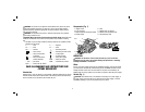
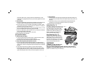
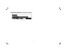
Parking Foot (Fig. 11)
Your planer is equipped with a parking foot (S)
FIG. 11
S
that automatically lowers into place when the
tool is lifted from the work surface. When
planing, the parking foot raises as the tool is
pushed forward. When the parking foot is
lowered, the planer can set on the work
surface without the blade touching.
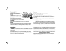
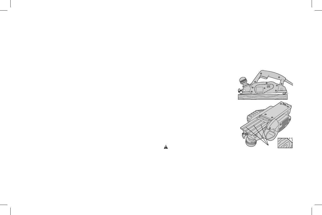
Edge Chamfering (Fig. 12)
Your planer has three precision machined
T
FIG. 12
chamfering grooves (T) in the front shoe for
planing along a corner of the wood (Fig. 12).
The width of the grooves are 1.5 mm, 2 mm,
and 2.5 mm. It’s a good idea to try a piece of
scrap wood before doing finish work.
MAINTENANCE
WARNING: To reduce the risk of injury,
turn unit off and disconnect tool from
power source before installing and removing accessories, before adjusting or
changing set-ups or when making repairs. Be sure the trigger switch is in the OFF
position. An accidental start-up can cause injury.