


English
3
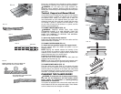
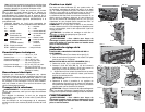
Depth Adjustment Crank Handle
TO ATTACH THE DEPTH ADJUSTMENT CRANK
HANDLE
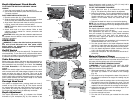
1. Insert the crank handle (F) over the shaft (Fig. 5).
2. Secure the crank handle in place with the star screw and
T-wrench provided.
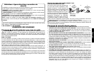
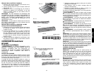
DUST HOOD INSTALLATION (FIG. 1)
1. Remove screws (AA, fig. 1), save these screws.
2. Slide the dust hood clips (BB, fig. 1A) into place on front
of the tool tray and rotate dust hood into place.
3 Align holes in dust hood with holes in tool tray and motor
housing, secure with screws removed earlier.
NOTE: Tighten the bottom screw first and then the two
side screws.
4. Attach dust hood to a dust collector. Refer to dust
collector owner's manual for correct procedure and
safety information.
CAUTION: When using the dust collection attachment do
not operate the unit without a hose connected and a dust
collector in operation.
OPERATION
WARNING: To reduce the risk of serious personal injury,
turn tool off and disconnect tool from power source
before making any adjustments or removing/installing
attachments or accessories.
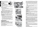
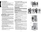
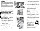
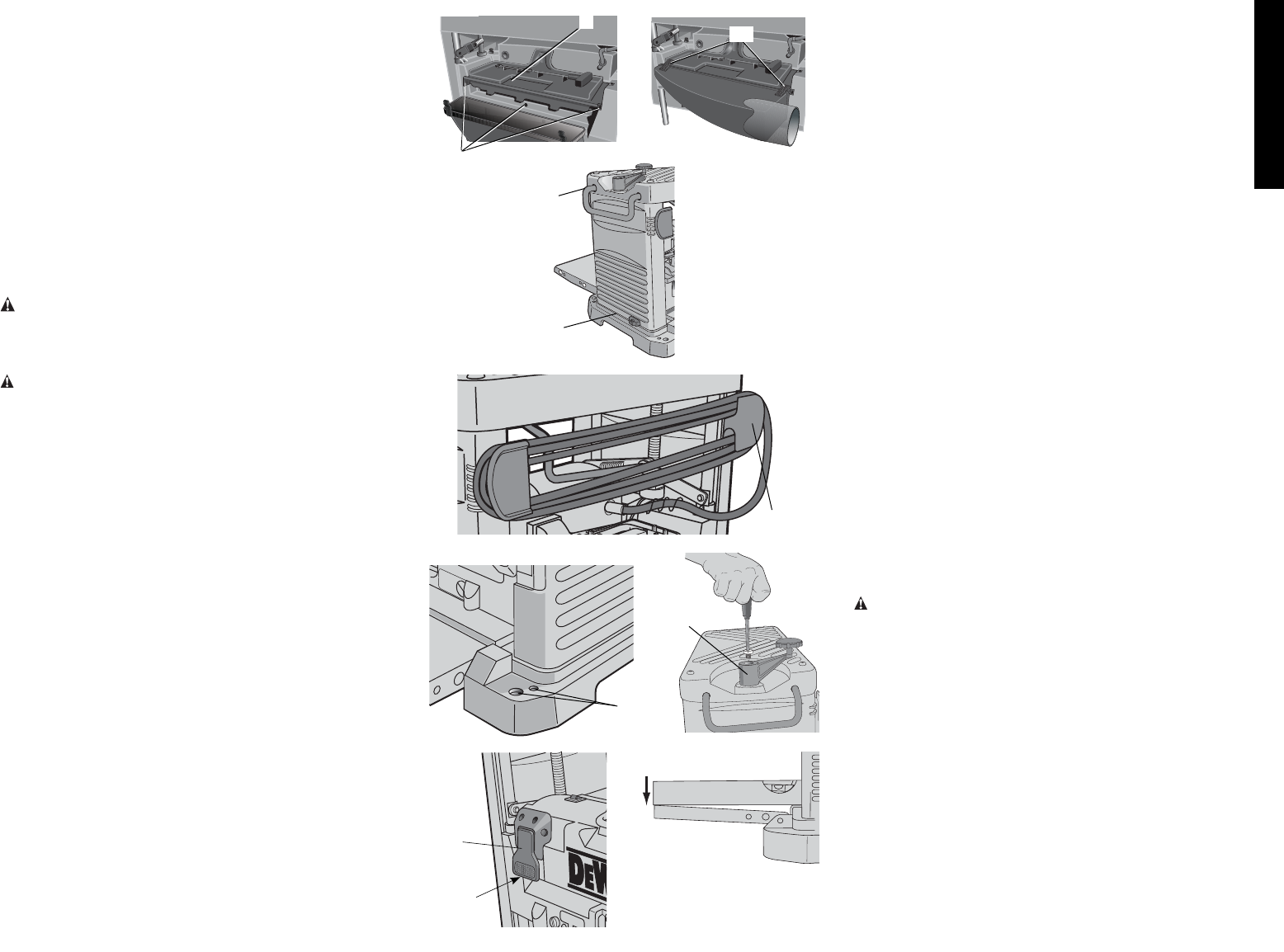
On/Off Switch
To turn the planer on, lift up the switch (G). The planer locks
on automatically. To turn the tool off, press the switch down.
A hole (H) is provided on the underside of the switch to insert
a padlock to lock off the planer as shown in Figure6.
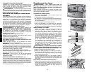
Table Extensions
Before using your planer, fold down the table extensions in
the front and back of the tool (Fig.7). After extended use, the
table extensions may be slightly out of level. See Leveling
the Table Extensions in the Maintenance section of this
manual.
NOTE: The outside edges of the extension tables are level
with the base while the inside edges (closest to the cutter
head) are below the edge of the base. This is set at the
factory to reduce unnecessary friction between the material
and the table while providing adequate support at the two
points (those farthest from the cutter head) on the tables
that are integral to snipe prevention.
Carriage Head Lock
Your planer is equipped with a carriage head lock lever (I)
located on top of the motor (Fig. 8). This device secures
the carriage that holds the cutter head to the four posts of
your planer. By locking the carriage to the four posts, the
movement that causes snipe is drastically minimized.
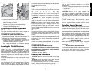
Depth Adjustment
The depth adjustment scale (J) indicates the finished
thickness of your workpiece (Fig. 9). One rotation of the
depth adjustment crank is equal to 1/16" (1.6mm); half a
rotation is equal to 1/32" (0.8mm), etc.
TO SET THE FINISHED THICKNESS
1. Raise head lock lever (I) to unlock the cutter head
(Fig.8). This allows the cutter head to be adjusted.
2. Adjust the thickness. Turn the depth adjustment handle
(F) clockwise to lower the cutter head. Turn the handle
counter-clockwise to raise the cutter head. One full
rotation of the handle moves the cutter head 1/16"
(1.6mm).
3. Depress the head lock lever to re-lock before planing.
NOTE: Do not attempt to adjust the carriage height while
the carriage lock is engaged. You may damage the machine.
FINE ADJUSTMENTS
The depth adjustment handle allows for fine adjustments,
from 1/64" (0.4mm) to 1/16" (1.6mm).
Fine adjustments are ideal for “shaving” small amounts
from your material. For example, if your planed workpiece
measures 3-1/16" (77.8 mm) thick, but should be 3"
(76.2 mm) thick, adjust your planer to remove the excess
1/16" (1.6mm) as follows:
1. Plane and measure your workpiece. In this example, the
finished thickness is 3-1/16" (77.8mm).
2. Turn the circular label on the depth adjustment handle
until the “0” mark aligns with the arrow on the top of the
tool. Do not make any other adjustments to the planer.
3. Turn the depth adjustment handle clockwise until the
1/16" (1.6mm) mark aligns with the arrow.
4. Plane your workpiece. The final thickness should be 3"
(76.2mm).
Material Removal Gauge
Your planer is equipped with a material removal gauge. It is
used to indicate the amount of wood that will be removed in
one pass with the carriage set at its current height.
TO USE THE MATERIAL REMOVAL GAUGE
WARNING: DO NOT SWITCH THE UNIT ON WITH
THE MATERIAL POSITIONED UNDER THE CARRIAGE.
SERIOUS INJURY COULD RESULT.
1. Slide approximately 3" (76.2mm) of your material under
the arrow (K) located in the middle of the carriage
(Fig.10).
2. The wood must lay flat against the base of the planer. If
the material is inserted at an angle, the reading may be
inaccurate.
3. Unlock and crank the carriage down on the material until
the material removal bar engages the wood. The red
indicator (L) moves up the scale indicating the amount of
material to be removed with the carriage at that height.
4. Adjust the carriage height until the desired depth of cut
appears on the gauge.
5. Pull the material out from under the carriage.
6. Lock the carriage lock lever.
7. Turn the unit on and feed your material into the cutter
head.
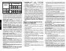
FIG. 2
C
B
FIG. 3
D
FIG. 4
E
FIG. 6
G
H
FIG. 7
FIG. 5
F
A
FIG. 1
AA
FIG. 1A
BB