


English
6
CHANGE BLADES WHEN:
• dull – may cause feeding issues.
• slow feed or no feed.
• motor overloading can also be an indication that knives
are dull and result in frequent breaker trips.
• excessive tearout of the wood material being planed
• nicked – blades can become nicked when planning very
knotty wood or when foreign material is not removed
from the wood being planed.
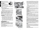
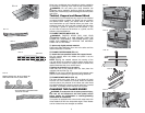
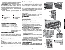
TO CHANGE PLANER KNIVES
1. Use the T-wrench to remove the tool tray. The cutter
head should now be exposed.
If the eight bolts in the knife clamp ARE NOT visible,
use a piece of scrap wood to carefully rotate the cutter
head until the bolts are accessible and the cutter head
locking lever engages as shown in Figure 21 (O). This will
prevent further rotation of the cutter head as you change
each knife (Fig.17).
If the bolts ARE visible, be sure that the cutter head
locking lever is engaged so the cutter head does not
rotate while you are changing the knives. To do this, use
a piece of scrap wood to attempt to rotate the cutter
head. The locking lever will click into place if it is not
already engaged.
WARNING: KEEP YOUR FINGERS AWAY FROM
THE CUTTER HEAD AT ALL TIMES. USE THE TOOL
PROVIDED TO HANDLE THE KNIVES.
2. Remove bolts from knife clamp.
3. Use the magnets on the top of the T-wrench to attract
the knife clamp and lift the knife off the cutter head
(Fig.18). One of the knives should now be exposed.
4. Use the magnet on the top of the T-wrench to attract
and handle the knife. AVOID TOUCHING THE KNIFE
WITH YOUR FINGERS. The knives on your planer are
sharpened on both edges.
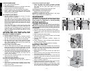
If only one edge of the knife is worn:
1. Turn the knife around so that the sharp, unused edge
hangs over the edge of the cutter head where it will cut
the material. Be sure to set the oblong holes in the knife
over the pins machined on the cutter head (Fig.19).
2. To reset the knife clamp, align the beveled edge of the
knife clamp with the cutting edge of the knife (Fig.20).
If these are not aligned correctly, the clamp will not
secure the knife properly.
3. Place the screws through the holes in the knife clamp
and knife into the cutter head.
4. Tighten the screws sufficiently.
To access and replace the other two knives:
1. Depress the cutter head lock lever (O) as shown in
Figure21.
2. Use the piece of scrap wood to carefully turn the cutter
head until it locks into place revealing another knife
clamp and dull knife.
3. Repeat the procedure indicated above.
FIG. 22
P
S
T
FIG. 26
FIG. 23
Q
FIG. 24
R
FIG. 25
If the knives are dull on both edges:
1. Follow the same knife change procedure indicated
above. HOWEVER, discard the dull knives and install
new ones onto the cutter head. Blades can not be
sharpened.
2. Repeat the procedure for the remaining knives.
After installing or reversing the knives:
1. Replace the tool tray onto the unit.
2. Tighten the screws onto the tray.
NOTE: THE PLANER WILL NOT OPERATE IF THE TOOL
TRAY IS NOT INSTALLED CORRECTLY.
MAINTENANCE
WARNING: To reduce the risk of serious personal injury,
turn tool off and disconnect tool from power source
before making any adjustments or removing/installing
attachments or accessories.
Periodic Maintenance
WARNING: To reduce the risk of serious personal injury,
turn tool off and disconnect tool from power source before
making any adjustments or removing/installing attachments
or accessories.
1. Routinely check the tool for damage or broken parts.
2. Clean the unit of dust and debris that has collected in
all accessible areas of the planer from planning wood
material.
3. Wipe off infeed and outfeed rollers.
4. Clean base table. Light waxing will help wood material
pass through the planer.
5. Evaluate blade sharpness condition. Replace as
necessary.
6. Gauge Calibration, check thickness gauge calibration
and turret stop calibration.
7. Check brushes for wear and replace as necessary.
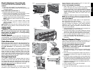
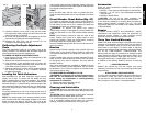
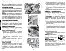
Installing a New Belt
NOTE: No tools are necessary to install a belt. The use of a
screwdriver or other tool to pry or stretch a belt may cause
damage to the pulleys and ultimately destroy the new belt.
1. Remove the crank handle.
2. Remove the two hex screws from the top, right side of
the planer.
3. Remove the two, small cross head screws securing the
side panels to the top of the planer.
4. Lift the side panel up out of the slot in the base and
remove the panel from the machine. Notice the grooves
inside the belt.
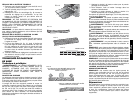
5. Start the belt on the top pulley (P) with 3 grooves on the
pulley, as shown in Figure 22.
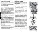
6. Guide the belt between the lower pulley and the height
adjustment screw (Q), as shown in Figure 23.
7. With three grooves engaged on the large pulley, rotate
the pulley clockwise. Keep pressure on the edge of the
belt to keep the grooves engaged on the small pulley.