


B
English
3
INTRODUCTION
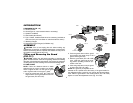
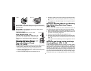
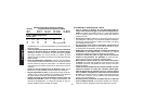
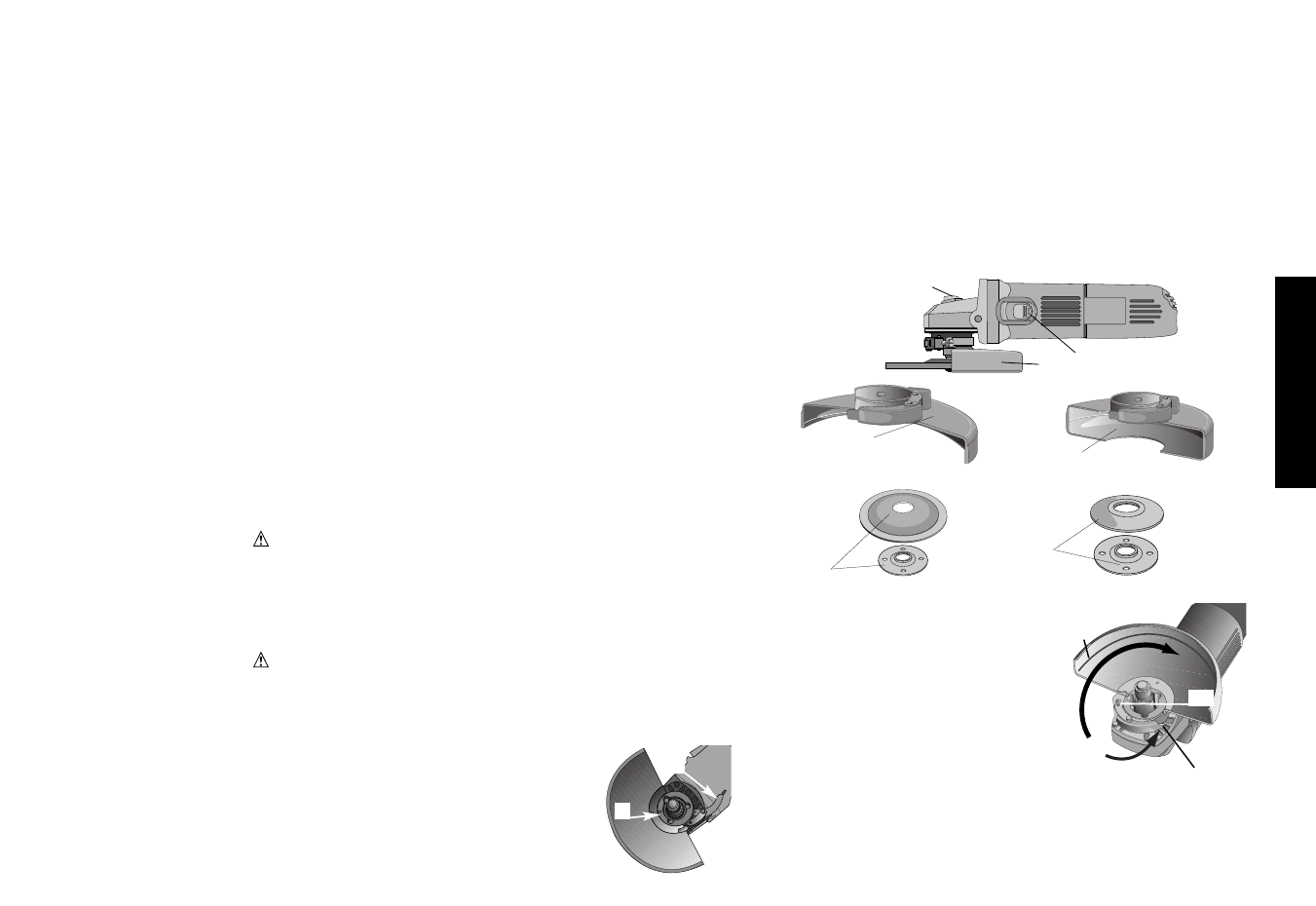
COMPONENTS (FIG. 1-5)
A. ON/OFF Switch
B. Guard (Type 27, open beneath wheel or accessory)
C. Spindle Lock Button
D. Side Handle (Not Shown)
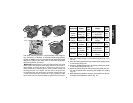
E. Type 1 Guard, closed beneath wheel or accessory (available at
extra cost from your local dealer or authorized service center.)
F. Matching Flanges
G. Depressed Center Flanges (for DW827 only)
ASSEMBLY
CAUTION: Turn off and unplug the tool before making any
adjustments or removing or installing attachments or accessories.
Before reconnecting the tool, depress and release the rear part of
the switch to ensure that the tool is off.
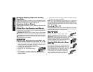
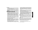
Fitting and Removing the Guard
(FIG. 6-7)
CAUTION: Unplug the tool before mounting or removing the
guard. Guards must be used with all grinding wheels and sanding
flap discs, wire brushes and wire wheels. The tool may be used with-
out the guard only when sanding with conventional sanding discs.
FITTING GUARD
NOTE: Follow the directions below to attach
either the type 27 or type 1 guard to your grinder.
Refer to figures 6 and 7 for the type 27 guard
and to figures 8 and 9 for the type 1 guard.
1. Open the guard latch (FIG. 6E or 8E) and
align the arrow on the guard with the arrow on
the gear case (FIG. 6F or 8F).
2. Push the guard down until the guard
lugs engage and rotate freely in the
groove on the gear case.
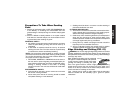
3. With the guard latch (FIG. 7B or 9B)
open, rotate the guard into the work-
ing position providing maximum pro-
tection to the user .
4. Close the guard latch to secure guard
on gear case (FIG. 7E or 9E).
NOTE: The guard is pre-adjusted to the
diameter of the spindle hub at the factory. If the guard needs fur-
ther adjustment after a period of use, perform the following adjust-
ment. With the guard latch in the closed position (FIG. 7E or 9E)
tighten or loosen the adjustment screw (Fig. 7H or 9H).
A
B
C
FIG. 1
FIG. 2
G
FIG. 4
F
FIG. 5
E
FIG. 3
FIG. 6
F
E
FIG. 7
B
E
H