7
English
A
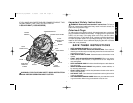
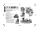
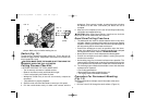
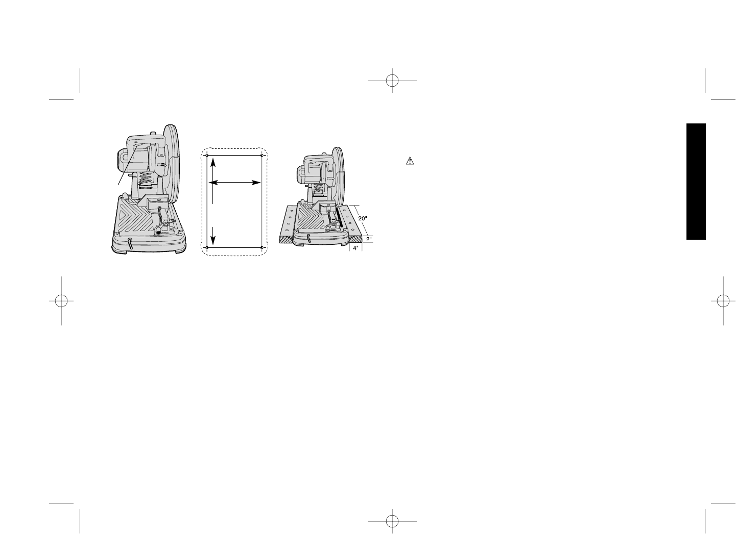
FIG. 13
FIG. 14
10-1/8"
(257 MM)
FIG. 15
17-3/8"
(441 MM)
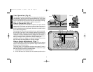
blade extends into the base.
3. Place a square (C) against the blade (D), adjust the fence against
the square and then re-lock the fence.
4. Unlock and raise the arm.
5. Loosen the two angle plate screws (E). Align the 0˚ pointer with
the edge of the slot (B) and retighten the screws.
Chip Deflector Adjustment (Fig. 8)
To aim chips away from surrounding area or into a collection bin,
loosen the screw (A), adjust the chip deflector (B) angle and retighten
the screw.
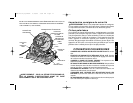
Auxiliary Vertical Clamp (Fig. 9)
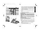
The auxiliary vertical clamp (A) MUST be used with the vise when
cutting wide or irregular shaped materials, when making angle cuts,
and when the fence is in the rear positions where the upstroke of the
blade tends to pull the workpiece up from the vise.
To use the clamp, insert it in one of the holes (Fig. 11,G) in the base
until the clamp rests on the workpiece. Press the lever down as
shown in Fig. 9 to lock the workpiece in place. Lift the lever to release
the clamp.
NOTE: When clamping thin stock, a shim of suitable thickness may
be required under the clamp pad.
WARNING: Failure to use vertical clamping when cutting on the
upstroke of the blade may result in serious damage to the tool and
possible personal injury.
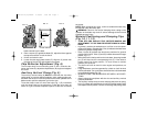
Material Positioning and Clamping Tips
(Fig. 10, 11, 12)
• TURN OFF AND UNPLUG TOOL BEFORE MAKING ANY
ADJUSTMENT TO THE SAW OR REPOSITIONING A WORK-
PIECE.
• In general, position the workpiece so it will be cut on the down-
stroke of the blade. (Shaded area) Slot (A) indicates the best fence
position for general cutting at 90˚.
• Slots (A) and (B) indicate the best fence positions for general
cutting at 90˚ and 45˚. Slots (C) and (D) indicate the same for larger
pieces. (Fig. 11)
• When the fence is lined up with a slot in the base, the spring loaded
pin (E) will drop into the corresponding hole (F) in the base to
further secure the fence position. To move fence to another
position, pull up the pin.
• The fence can also be used in other angles and positions, as
needed.
• Long workpieces must be supported by a block so it will be level
with the saw table The cut off piece should be free to fall downward
to avoid blade binding.(Fig. 12)
• ALWAYS CLAMP THE WORKPIECE SECURELY, NO EXCEP-
TIONS.
• Always clamp the workpiece with the vise and auxiliary vertical
clamp as described.
• The auxiliary vertical clamp or other clamping aids such as spring,
bar or C-clamps will compliment the vise for holding certain sizes
and shapes of work pieces. Use care in selecting and placing these
392736-01,00,DW872 6/29/00 9:00 AM Page 7


