


A
B
D
C
DWD215G
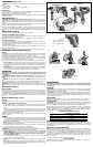
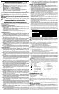
COMPONENTS (Fig. 1, 6)
WARNING: Never modify the power tool or any part of it. Damage or personal injury could
result.
A. Trigger switch D. Chuck
B. Reversing lever E. Indicator light (DWD220)
C. Side handle
INTENDED USE
These heavy-duty drills are designed for professional drilling applications. DO NOT use under
humid conditions or in presence of flammable liquids or gases.
These heavy-duty drills are professional power tools.
DO NOT let children come into contact with the tool. Supervision is required when inexperienced
operators use this tool.
Side Handle (Fig. 1)
WARNING: To reduce the risk of personal injury, ALWAYS operate the tool with the side
handle properly installed and tightened. Failure to do so may result in the side handle slipping
during tool operation and subsequent loss of control. Hold tool with both hands to maximize
control.
A side handle (C) is supplied with your drill. The side handle clamps to the front of the gear case
and can be rotated 360 degrees to permit right- or left-hand use.
After the side handle is rotated into position, it should be pushed rearward until the slots (H)
on the lip of the side handle are aligned and fully engaged with the projecting tabs (G) on the
underside of the gear case. The side handle is then securely clamped by turning clockwise until
tight.
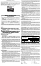
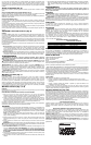
Trigger Switch (Fig. 2)
To start drill, depress trigger switch (A); to stop the drill, release trigger.
VARIABLE SPEED TRIGGER SWITCH (FIG. 2)
The variable speed trigger switch (A) permits speed control. The farther the trigger switch is
depressed, the higher the speed of the drill.
NOTE: Use lower speeds for starting holes, drilling in plastics or ceramics or driving screws.
REVERSING LEVER (FIG. 2)
The reversing lever (B), located above the trigger switch, changes the direction of rotation of the
drill and is used when backing out screws and jammed drill bits.
To operate the tool in reverse, release the trigger switch and push the lever to the left (when
viewed from the chuck end).
To operate the drill in forward, release the trigger switch and push the lever to the right (when
viewed from the chuck end).
Return the reversing lever to the forward position after all operations in reverse are completed.
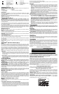
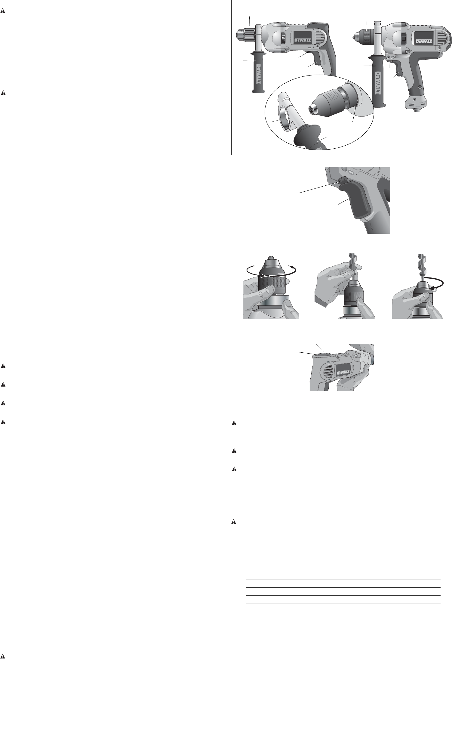
E-CLUTCH™ Anti-Lock Control (Fig. 6)
DWD220
Your D
EWALT drill may come with an electronic feature called E-CLUTCH™ Anti-Lock Control. It
is designed to help you control the drill during a stall and keep it from pulling out of your hands.
This may be encountered when drilling in steel or using large bits in wood.
As a stall situation presents itself, the motor cycles on and off for a set period of time. This takes
up the reaction of the stall and allows you to keep the drill under control. The speed control
senses your release of the trigger and resets the motor to run again.
Figure 6 shows the instruction label (H) mounted on the housing. There are two alert modes.
1. Engaged Mode: When a stall situation presents itself, the light will come on and stay on
as the motor cycles on and off for a set period of time before the E-CLUTCH™ Anti-Lock
Control completely shuts the tool down. When the unit is running in normal mode, there will
be no light.
2. Problem Mode: A series of continual flashes as the trigger is pulled indicates that the elec-
tronics are no longer functioning. The tool may still be able to function without the benefit of
E-CLUTCH™ Anti-Lock Control but should be serviced as soon as possible.
OPERATION
WARNING: To reduce the risk of serious personal injury, turn tool off and disconnect tool
from power source before making any adjustments or removing/installing attachments
or accessories.
WARNING: To reduce the risk of personal injury, ALWAYS ensure workpiece is anchored
or clamped firmly. If drilling thin material, use a wood “back-up” block to prevent damage to the
material.
WARNING: To reduce the risk of personal injury, ALWAYS operate the tool with the side
handle properly installed. Failure to do so may result in the side handle slipping during tool
operation and subsequent loss of control. Hold tool with both hands to maximize control.
WARNING: Do not attempt to tighten or loosen drill bits (or any other accessory) by gripping
the front part of the chuck and turning the tool on. Damage to the chuck and personal injury may
occur.
Keyed Chucks (Fig. 1)
DWD210G, DWD220
Open chuck jaws by turning collar with fingers and insert shank of bit about 3/4" (19 mm) into
chuck. Tighten chuck collar by hand. Place chuck key in each of the three holes, and tighten in
CLOCKWISE direction. It’s important to tighten chuck with all three holes to prevent slippage.
To release bit, turn chuck key COUNTERCLOCKWISE in just one hole, then loosen the chuck
by hand. Any authorized D
EWALT service center can install a keyless chuck in place of a keyed
chuck.
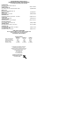
Keyless Chucks (Fig. 1, 3–5)
DWD215G
The DWD215G features a keyless chuck with one rotating sleeve for one-handed operation of
the chuck.
TO INSERT A DRILL BIT OR OTHER ACCESSORY
1. Grasp the black sleeve of the chuck (D) with one hand and use the other hand to secure
the tool. Rotate the sleeve counterclockwise far enough to accept the desired accessory
(Fig. 3).
2. Insert the accessory about 3/4" (19 mm) into the chuck and tighten securely by rotating the
chuck sleeve clockwise with one hand while holding the tool with the other hand. Continue to
rotate the chuck sleeve until several ratchet clicks are heard to ensure full gripping power.
To release the accessory, repeat Step 1 above.
Be sure to tighten chuck with one hand on the chuck sleeve and one hand holding the tool for
maximum tightness.
Drilling
1. Use sharp drill bits only. For WOOD, begin with low speed and use twist drill bits, spade bits,
power auger bits or hole saws. For METAL, begin with low speed and use steel twist drill bits
or hole saws.
Use a cutting lubricant when drilling metals. The exceptions are cast iron and
brass which should be drilled dry.
NOTE: Large [5/16" (8 mm) to 1/2" (13 mm)] holes in steel can be made easier if a pilot hole
[5/32" (4 mm) to 3/16" (5 mm)] is drilled first.
2. Always apply pressure in a straight line with the bit. Use enough pressure to keep drill biting,
but do not push hard enough to stall the motor or deflect the bit.
3. Hold tool firmly with both hands to control the twisting action of the drill.
WARNING: Drill may stall if overloaded causing a sudden twist. Always expect the stall. Grip
the drill firmly with both hands to control the twisting action and avoid injury.
4. IF DRILL STALLS, it is usually because it is being overloaded or improperly used. RELEASE
TRIGGER IMMEDIATELY, remove drill bit from work, and determine cause of stalling. DO
NOT CLICK TRIGGER ON AND OFF IN AN ATTEMPT TO START A STALLED DRILL —
THIS CAN DAMAGE THE DRILL.
5. To minimize stalling or breaking through the material, reduce pressure on drill and ease the
bit through the last fractional part of the hole.
6. Keep the motor running when pulling the bit back out of a drilled hole. This will help prevent
jamming.
7. With variable speed drills there is no need to center punch the point to be drilled. Use a
slow speed to start the hole and accelerate by squeezing the trigger harder when the hole
is deep enough to drill without the bit skipping out.
FIG. 1
MAINTENANCE
WARNING: To reduce the risk of serious personal injury, turn tool off and disconnect tool
from power source before making any adjustments or removing/installing attachments
or accessories.
Cleaning
WARNING: Blow dirt and dust out of all air vents with dry air at least once a week. Wear
proper ANSI Z87.1 (CAN/CSA Z94.3) eye protection and proper NIOSH/OSHA/MSHA
respiratory protection when performing this.
WARNING: Never use solvents or other harsh chemicals for cleaning the non-metallic parts
of the tool. These chemicals may weaken the plastic materials used in these parts. Use a cloth
dampened only with water and mild soap. Never let any liquid get inside the tool; never immerse
any part of the tool into a liquid.
Lubrication
Self-lubricating bearings are used in the tool and periodic relubrication is not required. In the
unlikely event that service is ever needed, take your tool to an authorized service location.
Accessories
WARNING: Since accessories, other than those offered by DEWALT, have not been tested
with this product, use of such accessories with this tool could be hazardous. To reduce the risk
of injury, only D
EWALT, recommended accessories should be used with this product.
Recommended accessories for use with your tool are available at extra cost from your local dealer
or authorized service center. If you need assistance in locating any accessory, please contact
D
EWALT Industrial Tool Co., 701 East Joppa Road, Baltimore, MD 21286, call 1-800-4-DEWALT
(1-800-433-9258) or visit our website www.dewalt.com.
MAXIMUM RECOMMENDED CAPACITIES
DWD210G/DWD215G/DWD220
CHUCK CAPACITY 1/2" (13 mm)
R.P.M. 0-1,200
BITS, METAL DRILLING 1/2" (13 mm)
WOOD, FLAT BORING 1-1/2" (40 mm)
Repairs
To assure product SAFETY and RELIABILITY, repairs, maintenance and adjustments (including
brush inspection and replacement) should be performed by a D
EWALT factory service center,
a DEWALT authorized service center or other qualified service personnel. Always use identical
replacement parts.
Three Year Limited Warranty
DEWALT will repair, without charge, any defects due to faulty materials or workmanship for
three years from the date of purchase. This warranty does not cover part failure due to normal
wear or tool abuse. For further detail of warranty coverage and warranty repair information, visit
www.dewalt.com or call 1-800-4-D
EWALT (1-800-433-9258). This warranty does not apply to
accessories or damage caused where repairs have been made or attempted by others. This
warranty gives you specific legal rights and you may have other rights which vary in certain
states or provinces.
In addition to the warranty, D
EWALT tools are covered by our:
1 YEAR FREE SERVICE
D
EWALT will maintain the tool and replace worn parts caused by normal use, for free, any time
during the first year after purchase.
FIG. 3
FIG. 4
FIG. 5
D
FIG. 2
B
shown in forward position
illustré en position avant
aparece en posición normal
A
DWD210G, DWD220
A
B
D
C
C
H
G
H
E
FIG. 6
DWD220