


N
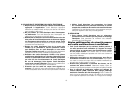
FIG. 8
FIG. 9
F
G
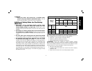
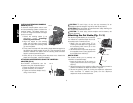
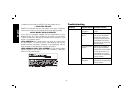
CUT GUIDE
This feature allows you to more accurately track a marked cut line.
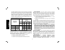
1. Insert the guide arm (G) as shown in Figure 10 into the slots on
the left and right sides of the guide block (F).
2. Adjust the length of the guide by pulling out or pushing inward to
achieve the desired length as shown in Figure 11.
3. Secure the guide in place by turning the depth/cut adjustment
knob (N) clockwise. To release the guide, turn the depth/cut
adjustment knob counterclockwise.
N
FIG. 10 FIG. 11
F
G
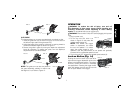
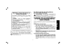
NOTE: The guide arm can also be placed in
FIG. 12
the guard assembly vertically in order to set
the height of a cut. Refer to Figure 12.
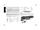
OPERATION
WARNING: To reduce the risk of injury, turn unit off
and disconnect it from power source before installing and
removing accessories, before adjusting or when making
repairs. An accidental start-up can cause injury.
WARNING: Ensure switch is fully OFF before plugging in the power
cord.
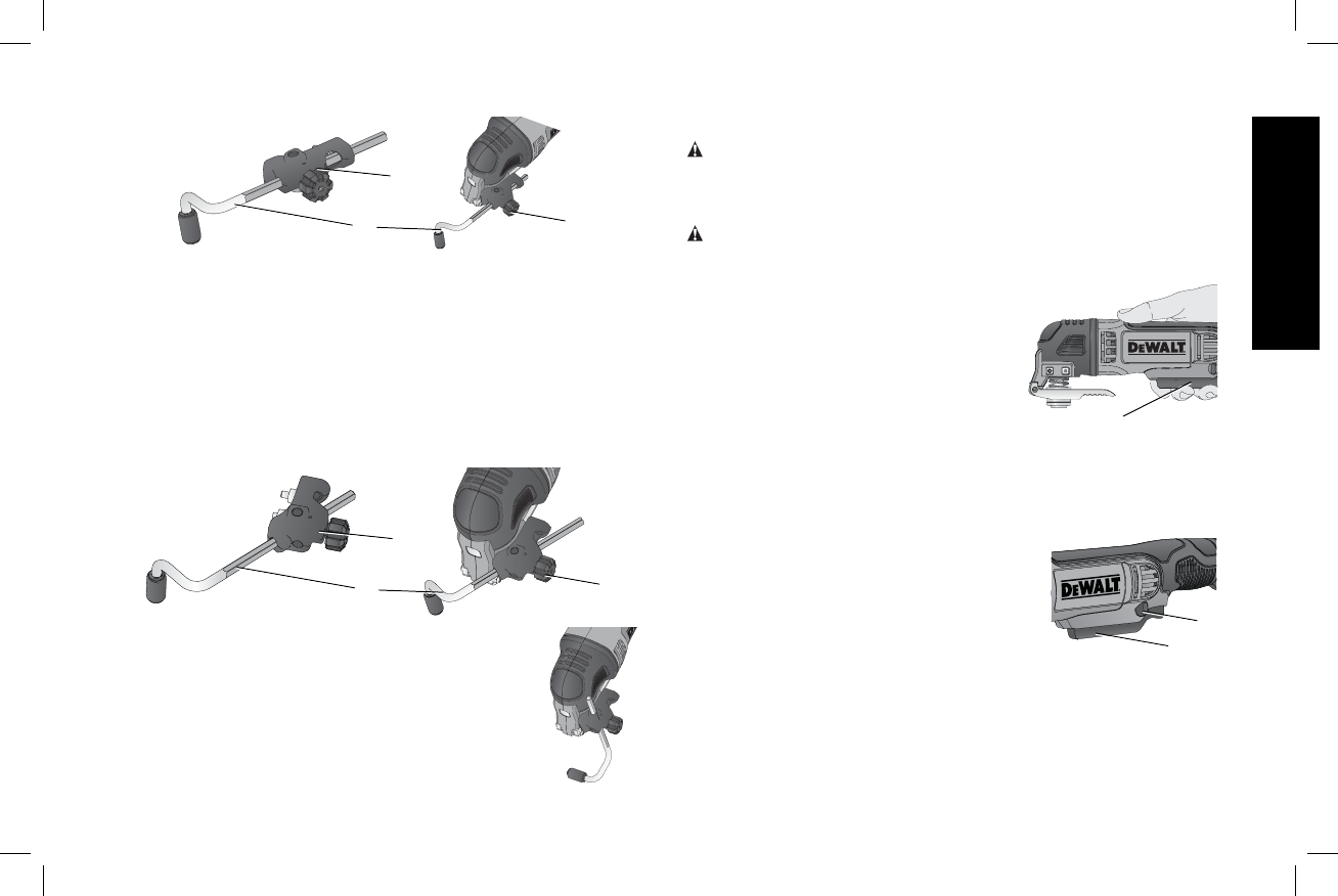
1. Plug in power cord.
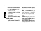
FIG. 13
A
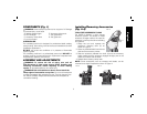
2. To turn the tool ON, hold it as
shown in Figure 13 and press the
variable speed trigger (A).
NOTE: The further the trigger
switch is depressed, the faster
the tool will operate. If in doubt
about the proper speed for your
operation, test the performance at low speed and gradually
increase until a comfortable speed is found.
3. To turn the tool OFF, release the variable speed switch (A).
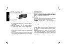
Lock-on Button (Fig. 14)
Pushing the lock-on button (D) to the left or
right with the trigger depressed will lock the
trigger in the depressed position. This allows
for more comfort and control in extended
use applications. Pressing the trigger switch
again will release the lock and the tool will
turn off upon release of the trigger.
FIG. 14
A
D
English
7