


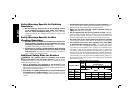
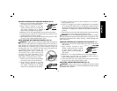
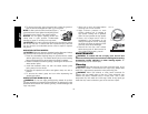
3. Keeping the guard release lever open, push the guard down until
engage the lugs and rotate them into the groove on the gear case
hub. Release the guard release lever.
4. With the spindle facing the operator, rotate
FIG. 5
the guard clockwise into the desired
working position. The guard body should
be positioned between the spindle and
the operator to provide maximum operator
protection.
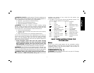
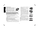
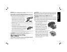
MOUNTING AND REMOVING (TYPE 27)
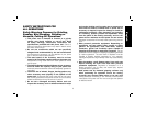
ONE-TOUCH™ GUARD (FIG. 4, 5)
NOTE: If your grinder is supplied with a
I
K
H
J
FIG. 4
keyless ONE TOUCH™ guard, ensure the
screw, lever, and spring are fitted correctly
before mounting the guard.
1. Press the guard release lever (H).
2. While holding the guard release lever open,
align the lugs (I) on the guard with the slots
on the gear case (J).
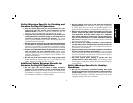
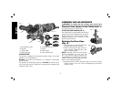
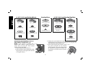
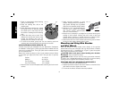
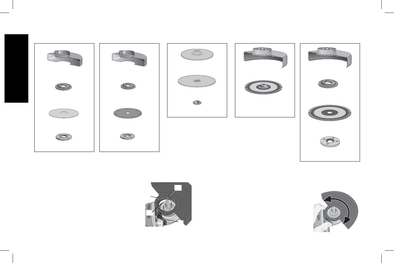
4-1/2" (114.3 mm) Cutting Wheels
Sanding Discs
4-1/2" (114.3 mm) Sanding Flap
Discs
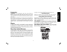
Type 1 guard
backing flange
abrasive cutting wheel
clamp nut
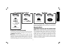
Type 1 guard
backing flange
diamond cutting wheel
clamp nut
rubber backing pad
sanding disc
threaded clamp nut
hubbed sanding
flap disc
Type 27 guard
backing flange
non-hubbed sanding
flap disc
threaded clamp nut
Type 27 guard
English
10