


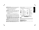
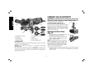
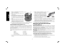
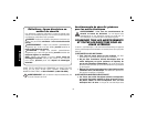
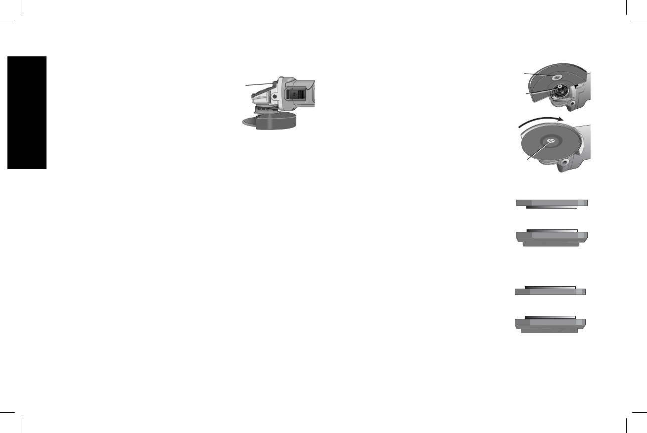
SPINDLE LOCK (FIG. 7)
The spindle lock button (A) is provided to
A
FIG. 7
prevent the spindle from rotating when
installing or removing wheels. Operate the
spindle lock only when the tool is turned off,
unplugged from the power supply, and has
come to a complete stop. Do not engage the
spindle lock button while the tool is operating
because damage to the tool will result. To
engage the lock, depress the spindle lock button and rotate the
spindle until you are unable to rotate the spindle further.
Mounting and Using Depressed Center
Grinding Wheels and Sanding Flap Discs
MOUNTING AND REMOVING HUBBED WHEELS
Hubbed wheels install directly on the 5/8"–11 threaded spindle.
Thread of accessory must match thread of spindle.
1. Remove backing flange (D) by pulling away from the tool.
2. Thread the wheel on the spindle by hand.
3. Depress the spindle lock button and use a wrench to tighten the
hub of the wheel.
4. Reverse the above procedure to remove the wheel.
NOTICE: Failure to properly seat the wheel before turning the tool on
may result in damage to the tool or the wheel.
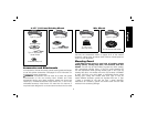
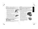
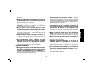
MOUNTING NON-HUBBED WHEELS (FIG. 8)
Depressed center Type 27 grinding wheels must be used with
included flanges. Refer to Accessories and Attachments for more
information.
1. Install the backing flange (D) on spindle (B) with the raised section
(pilot) against the wheel. Be sure the backing flange recess is
seated onto the flats of the spindle by
pushing and twisting the flange before
placing wheel.
2. Place wheel against the backing flange,
centering the wheel on the raised section
(pilot) of the backing flange.
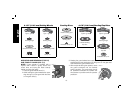
3. While depressing the spindle lock button,
thread the clamp nut (E) on spindle. If
the wheel you are installing is more than
1/8" (3.31 mm) thick, place the threaded
clamp nut on the spindle so that the
raised section (pilot) fits into the center of
the wheel. If the wheel you are installing
is 1/8" (3.31 mm) thick or less, place the
threaded clamp nut on the spindle so that
the raised section (pilot) is not against the
wheel.
4. While depressing the spindle lock button,
tighten the clamp nut with a wrench.
5. To remove the wheel, depress the spindle
lock button and loosen the threaded
clamp nut with a wrench.
NOTE: If the wheel spins after the clamp
nut is tightened, check the orientation of the
threaded clamp nut. If a thin wheel is installed
with the pilot on the clamp nut against the
wheel, it will spin because the height of the
pilot prevents the clamp nut from holding the
wheel.
1/4" WHEELS
(6.35 mm)
Backing Flange
Clamp Nut
1/8" WHEELS
(3.31 mm)
Backing Flange
Clamp Nut
D
B
E
FIG. 8
English
12