


ENGLISH
9
Mounting Guards
WARNING: To reduce the risk
of serious personal injury, turn
tool off and disconnect tool from
power source before making any
adjustments or removing/installing
attachments or accessories. Before
reconnecting the tool, depress and
release the trigger switch to ensure that
the tool is off. An accidental start-up can
cause injury.
CAUTION: Guards must be used with
this grinder.
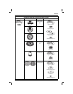
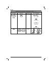
NOTE: Please refer to the Grinding and Cutting
Accessory Chart at the end of this section to
see other accessories that can be used with these
grinders.
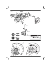
MOUNTING AND REMOVING (TYPE 27)
ONE-TOUCH GUARD (FIG. 2)
NOTE: If your grinder is supplied with a keyless
One-Touch guard ensure the screw and spring are
fitted correctly before mounting the guard
1. Press the guard release lever (h).
2. While holding the guard release lever open, align
the lugs (i) on the guard (f) with the slots on the
gear case (j).
3. Keeping the guard release lever open, push the
guard down until engage the lugs and rotate
them into the groove on the gear case hub.
Release the guard release lever.
4. With the spindle facing the operator, rotate
the guard clockwise into the desired working
position. The guard body should be positioned
between the spindle and the operator to provide
maximum operator protection.
5. For easy adjustment, the guard can be rotated
in the clockwise direction.
NOTE: The guard release lever should snap
into one of the alignment holes (k) on the guard
collar. This insures that the guard is secure.
The guard can be repositioned the opposite
direction by depressing the guard release lever.
6. To remove the guard, follow steps 1–3 of these
instructions in reverse.
MOUNTING AND REMOVING THE FIXED SCREW GUARD
(FIG. 3)
DWE4001
1. Place the angle grinder on a table, spindle (b)
up.
2. Align the lugs (i) with the notches (j).
3. Press the guard (f) down and rotate it to the
required position.
4. Securely tighten the screw (l).
5. To remove the guard, slacken the screw.
CAUTION: If the guard cannot be
tightened by the adjusting screw (l), do
not use the tool. To reduce the risk of
personal injury, take the tool and guard
to a service center to repair or replace
the guard.
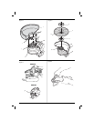
Fitting and Removing a Grinding Disc
(fi g. 1, 4)
WARNING: Do not use a damaged
disc.
1. Place the tool on a table, guard up.
2. Fit the backing flange (d) correctly onto the
spindle (b) (fig. 4).
3. Place the disc (n) on the backing flange (d).
When fitting a disc with a raised centre, make
sure that the raised centre (m) is facing the
backing flange (d).
4. Screw the threaded clamp nut (e) onto the
spindle (b) (fig. 4):
The ring on the threaded clamp nut (e) must
face towards the disc when fitting a grinding
disc.
5. Press the spindle lock button (a) and rotate the
spindle (b) until it locks in position.
6. Tighten the threaded clamp nut (e) with the hex
key provided or a two pin spanner.
7. Release the spindle lock.
8. To remove the disc, loosen the threaded clamp
nut (e) with the hex key provided or a two pin
spanner.
NOTE: Edge grinding can be performed with Type
27 wheels designed and specified for this purpose;
6 mm thick wheels are designed for surface grinding
while 3 mm wheels are designed for edge grinding.
Mounting Wire Brushes
andWire Wheels
Wire cup brushes or wire wheels screw directly on
the grinder spindle without the use of flanges. Use
only wire brushes or wheels provided with a M14
(DWE4050) or M10 (DWE4001) threaded hub. A
Type 27 guard is required when using wire brushes
and wheels.