


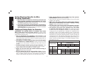
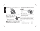
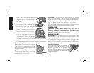
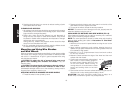
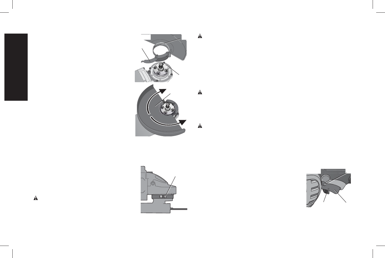
1. Open the guard latch (M), and align the
M
N
O
FIG. 6
F
lugs (N) on the guard with the slots on
the gear case (O). This will align the lugs
on the guard with the slots on the gear
case cover.
2. Push the guard down until the guard
lugs engage and can rotate freely into
the groove on the gear case hub.
3. With the guard latch open, rotate the
guard (F) into the desired working
position. The guard body should be
positioned between the spindle and the
operator to provide maximum operator
protection.
4. Close the guard latch to secure the
guard on the gear case. You should
not be able to rotate the guard by
hand when the latch is closed. Do not
operate the grinder with a loose guard or with the guard latch in
open position.
5. To remove the guard, follow the procedure above in reverse order.
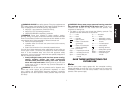
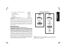
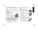
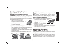
NOTE: The guard is pre-adjusted to the
P
FIG. 7
diameter of the gear case hub at the factory.
If, after a period of time, the guard becomes
loose, tighten the adjusting screw (P) with
guard latch in the closed position with guard
installed on the tool.
CAUTION: Do not tighten the adjusting
screw with the guard latch in the open
position. Undetectable damage to the guard
or the mounting hub may result.
CAUTION: If the guard cannot be tightened by the adjusting
clamp, do not use the tool. To reduce the risk of personal injury, take
the tool and guard to a service center to repair or replace the guard.
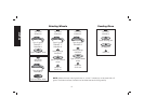
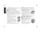
NOTE: Edge grinding and cutting can be performed with
Type 27 wheels designed and specified for this purpose; 1/4"
(6.35 mm) thick wheels are designed for surface grinding while 1/8"
(3.17 mm) wheels are designed for edge grinding. Cutting can also be
performed by using a Type 1 wheel and a Type 1 guard.
OPERATION
WARNING: To reduce the risk of injury, turn unit off
and disconnect it from power source before installing and
removing accessories, before adjusting or when making
repairs. An accidental start-up can cause injury.
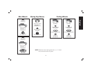
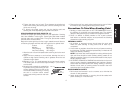
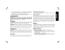
Switch (Fig. 8)
CAUTION: Before connecting the tool to a power source or after
a power failure, depress and release the trigger switch (A) once
without depressing the lock-on button (C) to ensure that the switch is
in the off position. If the trigger switch is locked on, the tool will start
unexpectedly when power is reconnected to the tool. Hold the side
handle and rear handle firmly to maintain control of tool at start up
and during use.
TRIGGER OPERATION
To turn the tool on, depress lock-off button (B)
A
B
C
FIG. 8
then trigger switch (A). The trigger can be
feathered as long as the lock-off button is
depressed. The tool will remain running while
the trigger is depressed. Turn the tool off by
releasing the trigger.
English
14