


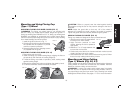

TRIGGER OPERATION WITH LOCK-ON FEATURE
To turn tool on, depress trigger. Depress and hold lock-on button (C)
while releasing trigger. Lock-on button will remain depressed and tool
will remain on.
To turn the tool off, depress and release trigger. The lock-on button
will pop out, permitting the trigger to disengage and causing the tool
to turn off.
NOTE: Allow the tool to reach full speed before touching tool to work
surface. Lift the tool from the work surface before turning the tool off.
CAUTION: Make sure the wheel has come to a complete stop
be fore setting the tool down.
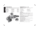
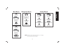
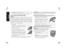
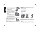
SPINDLE LOCK BUTTON (FIG. 9)
The spindle lock button (D) is provided to
FIG. 9
D
prevent the spindle from rotating when
installing or removing wheels.
NOTICE: To reduce the risk of damage to
the tool, do not engage the spindle lock
button while the tool is operating. Damage
to the tool will result and attached accessory
may spin off possibly resulting in injury.
To engage the lock, depress the spindle lock button (D) and rotate the
spindle until you are unable to rotate the spindle further.
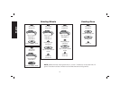
Mounting and Using Depressed Center
Grinding Wheels and Sanding Flap Discs
MOUNTING AND REMOVING HUBBED WHEELS
Hubbed wheels install directly on the 5/8"—11 threaded spindle.
1. Thread the wheel on the spindle by hand, seating the wheel
against the soft mount.
2. Depress the spindle lock button and use a wrench to tighten the
hub of the wheel.
3. Reverse the above procedure to remove the wheel.
CAUTION: Failure to properly seat the wheel against the soft
mount before turning the tool on may result in damage to the tool or
the wheel.
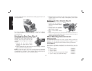
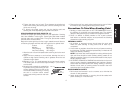
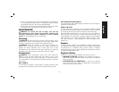
MOUNTING NON-HUBBED WHEELS
Depressed center, Type 27 grinding wheels
FIG. 10
Q
E
R
must be used with available accessory flanges.
See the chart on pages 11–13 of this manual
for more information.
1. Install the metal backing flange (Q) on
spindle (E) against the soft mount.
2. Place wheel against the backing flange,
centering the wheel on the backing flange
pilot.
3. While depressing the spindle lock button,
thread the clamp nut (R) on spindle,
piloting the raised hub on clamp nut in the
center of grinding wheel.
4. Tighten the clamp nut with a wrench.
5. Reverse the above procedure to remove the wheel.
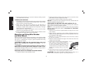
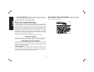
SURFACE GRINDING WITH GRINDING WHEELS (FIG. 11)
1. Allow the tool to reach full speed before
FIG. 11
20˚–30˚
touching the tool to the work surface.
2. Apply minimum pressure to the work
surface, allowing the tool to operate at
high speed. Grinding rate is greatest
when the tool operates at high speed.
3. Maintain a 20° to 30° angle between the tool and work surface.
English
15