


English
8
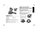
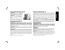
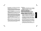
4. Ensure dust shroud (C) is seated
FIG. 4
G
C
against sander body and tighten
screw (G) so shroud does not
move while tool is running. Do not
overtighten.
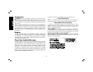
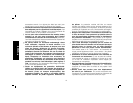
Assemble Sanding Pad
(Fig. 5)
1. Place supplied wrench (I) onto spindle. Rotate and align wrench
with dust shroud baffles (J).
2. While holding the spindle with the wrench, place sanding pad (K)
onto spindle and rotate counter clockwise until tight.
I
FIG. 5
J
K
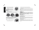
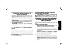
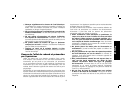
Attaching Abrasive Disc (Fig. 6)
Use 5" (127 mm) sanding discs with a
FIG. 6
5-hole dust extraction pattern which
attach to the sander with hook and
loop.
1. Turn the sander over so that the
sanding pad is facing upward.
2. Clean the dust from the hook and loop pad face.
3. Hold the pad with one hand to keep it from rotating.
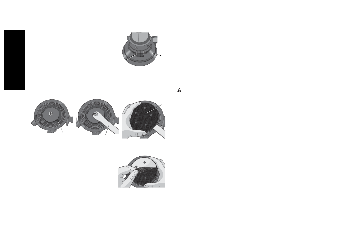
4. With the other hand, align the holes and place the disc directly on
top of the pad.
NOTE: Do not use the sanding screen (the screen used for sanding
drywall) directly on the hook and loop pad. The screen will not
hold and will damage the hooks on the pad. The hooks will wear
very rapidly if left in contact with the work surface while the tool is
operating.
OPERATION
WARNING: To reduce the risk of injury, turn unit off
and disconnect it from power source before installing and
removing accessories, before adjusting or when making
repairs. An accidental start-up can cause injury.
Switch (Fig. 1)
The variable speed is controlled in two ways: speed control dial (E)
and the trigger switch (F).
SPEED CONTROL DIAL
By rotating the speed control dial (E) in either direction, the maximum
speed or revolutions per minute at which the sander will perform is
adjusted. The speed control dial adjusts the rotation speed of the pad
from approx. 0 to 3700 rpms.
TRIGGER SWITCH
As the trigger switch is pressed in, the rotation continues to increase,
but will not exceed the maximum setting on the speed control dial.
As the trigger is released, the sander head revolutions per minute are
reduced.