3
bl a d e co n v e r s i o n kit in s t a l l a t i o n in s t r u c t i o n s
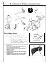
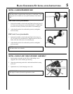
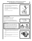
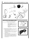
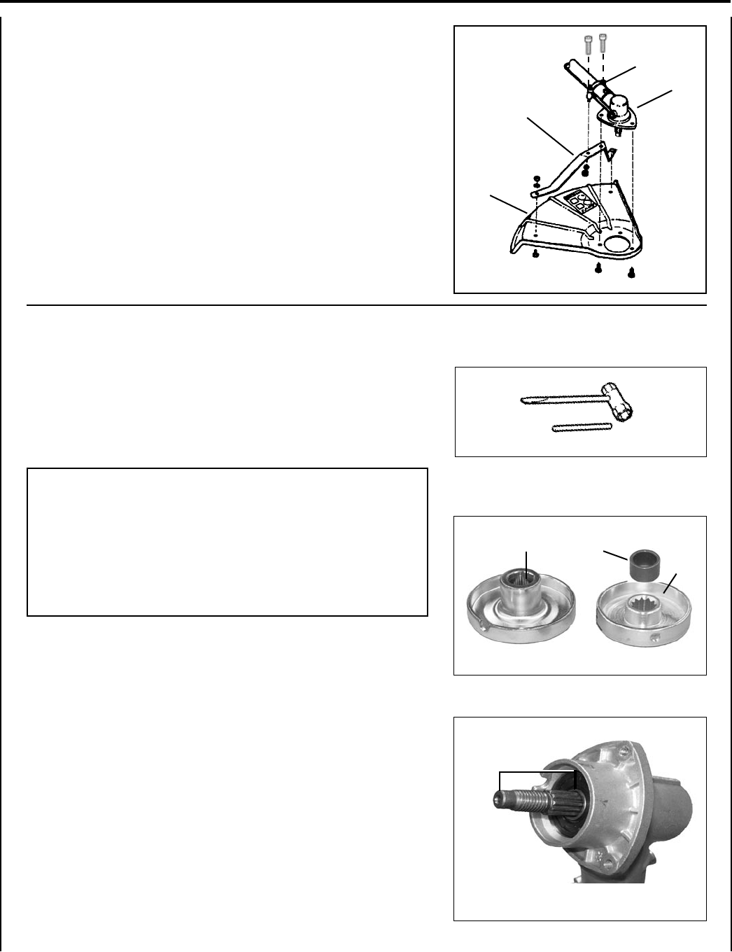
2. Loosely attach bracket (D) to shield (E) and attach shield to bottom
of gear housing (F) with hardware provided.
3. Remove gearcase clamping screws (G) and loosely attach bracket
(D) to gearcase (F) with 2 - 5x35mm screws, nuts and lockwashers
provided in kit.
4. Tighten all hardware.
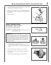
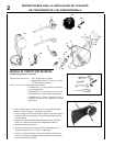
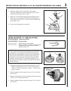
1. Check type of gear housing assembly on unit:
• Measure PTO shaft. If shaft is 32 mm, proceed to step 2. If
shaft is 42 mm, proceed to step 3. If shaft is 45 mm, proceed to
step 4.
2. Install short-necked upper xing plate (Y) onto PTO shaft.
3. Install shaft collar (Z) then short-necked upper xing plate (Y)
onto PTO shaft.
4. Install long-necked upper xing plate (X) onto PTO shaft.
IMPORTANT
This kit can be mounted on several different style gear housings.
A long-necked upper xing plate (X), a short-necked upper xing
plate (Y), and a10mm shaft collar (Z) are included in the kit, and
may be required to properly mount the blade. Failure to install the
correct upper xing plate conguration will cause the gearcase to
bind. Refer to the assembly instructions below to identify upper
xing plate assembly.
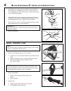
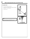
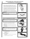
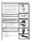
i n s t a l l o p t i o n a l b l a d e
Kit 99944200418 - Blade not included
Kit 99944200422 - Blade included
Tools Required: Locking Tool, T-Wrench.
Parts Required: Upper Fixing Plate w/ 20 mm pilot, Lower Plate, 10
mm Nut, Split Pin, Blade.
E
D
F
X
Y
Z
PTO
SHAFT
G


