


2.10
PK 255
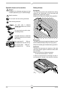
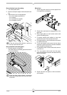
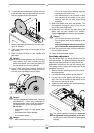
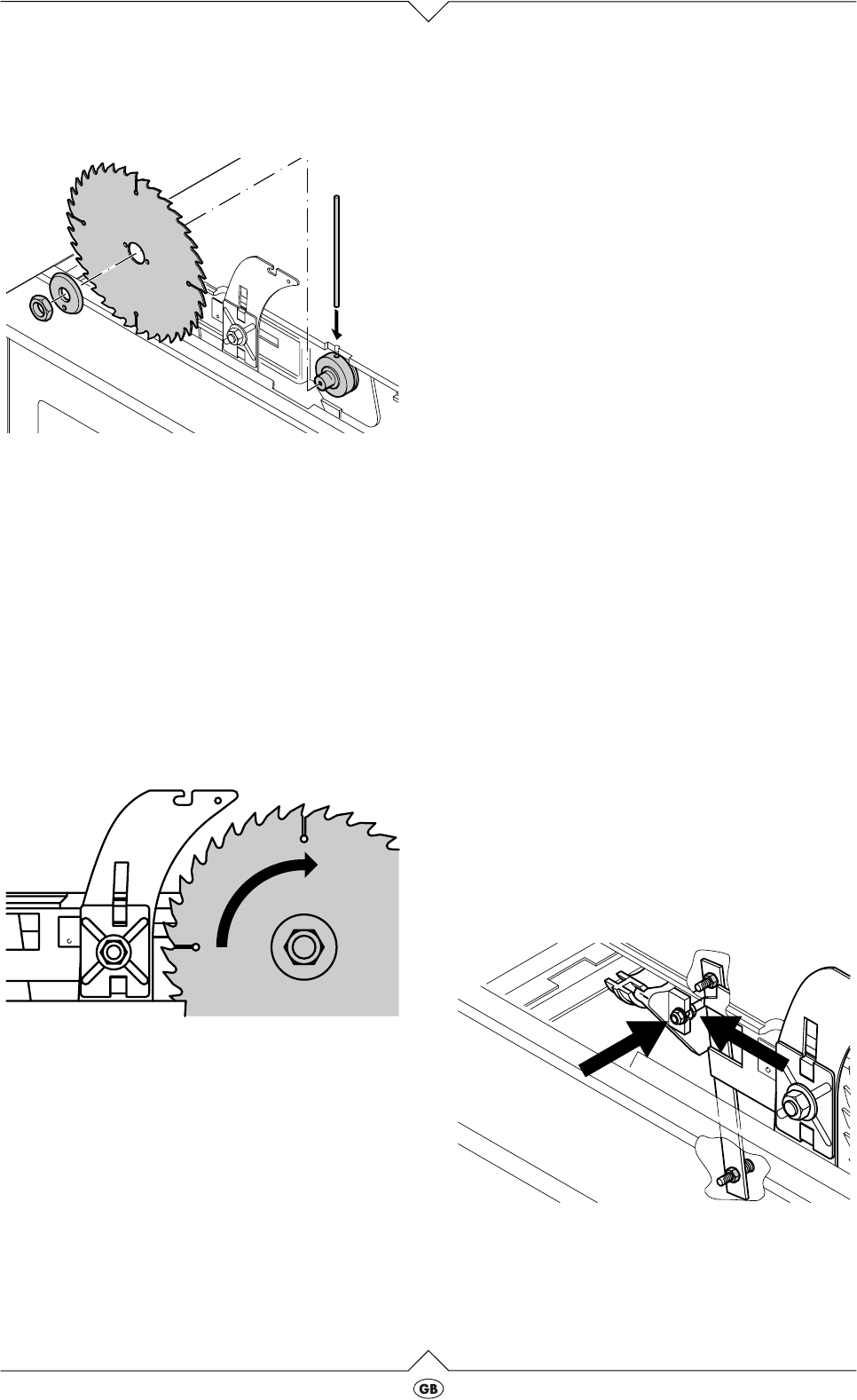
6. To block the saw blade insert lock bar into hole
in the saw table and turn saw blade by hand until
lock bar engages in saw spindle hole.
7. Loosen saw blade spindle arbor nut with span-
ner (L.H. thread!).
8. Take outer blade collar and saw blade off the
saw spindle.
9. Clean clamping surfaces of saw spindle and
saw blade.
A
Danger!
Do not use cleaning agents (e.g. for removing
resin residue) that could corrode the light
metal components of the saw; the stability of
the saw would be adversely affected.
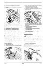
10. Put on a fresh saw blade (observe direction of
rotation). The saw spindle’s driving pin must fit
into one of the saw blade’s two pin holes.
A
Danger!
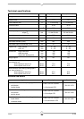
Use only suitable saw blades (see „Technical
specifications“) – when using unsuitable or
damaged blades parts could be explosive-
like hurled from it by the centrifugal force.
Do not use:
- saw blades made of high speed steel
(HSS);
- saw blades with visible damage;
- cut-off wheel blades.
A
Danger!
- Mount saw blade only using genuine parts.
- Do not use loose-fitting reducing rings; the
saw blade could work loose.
- Saw blades have to be mounted in such
way that they do not wobble or run out of
balance, and can not work loose during
operation.
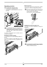
11. Slide outer blade collar onto saw spindle. The
saw spindle’s driving pin must fit into the pin
hole of the outer blade collar.
12. Screw arbor nut, with the low side facing the
blade, onto the saw spindle (L.H. thread!).
Tighten fingertight only with the tool supplied.
A
Danger!
- Do not extent the arbor nut wrench.
- Do not tighten arbor nut by tapping on the
wrench.
- After tightening the arbor nut do not for-
get to remove the saw spindle lock bar!
13. Slide chip case cover back into the closed posi-
tion and tighten screws.
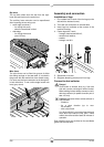
14. Fasten removable table section.
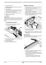
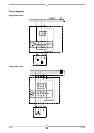
Saw blade adjustment
The saw blade must run exactly parallel with the
saw table’s edge. The distance between the table’s
edge and the blade shall be not more than 3 mm.
Adjustment is done from the top with setting nuts.
This setting is then fixed by two counter nuts on the
underside of the saw:
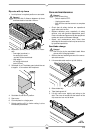
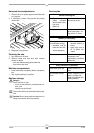
1. Remove the two fastening screws of the remov-
able table section.
2. Lift removable table section up and remove.
3. Lift chip case cover slightly and swing to the
side. The cover is hooked into the bottom of the
chip case and can not fall down.
4. Tighten two each setting nuts on the swivel seg-
ments against each other.
3
The swivel segments’ setting nuts must not
be tightened during operation of the saw,
as this would create mechanical twisting and
warping.