


9
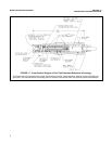
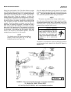
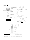
2.2.1 Flow Through and Insertion Mounting for
Models 396, 396VP, 398, and 398VP. The Models 396,
396VP, 398, and 398VP Sensors can be used with a 1
inch MNPT process connector at the front of the sensor
for mounting into a 1-1/2 inch tee or the process. See
Figure 2-1 for installation configurations.
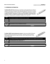
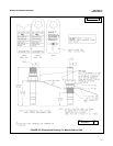
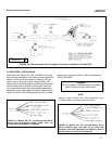
2.2.2 Submersion Mounting for Models 396, 396VP,
398, and 398VP. The Models 396, 396VP, 398, and
398VP Sensors also have a 1 inch MNPT process con-
nector available for use on the back of the sensor.
Tapered pipe threads in plastic fittings tend to loosen
after installation. It is therefore recommended that Teflon
tape be used on the threads and that the tightness of the
connection be checked frequently to assure that no loos-
ening has occurred. To prevent rain water or condensa-
tion from running into the sensor, a weatherproof junc-
tion box is recommended (see Figure 2-4). The sensor
cable must be run through a protective conduit for isola-
tion from electrical interference or physical abuse from
the process. The sensor should be installed within 80° of
vertical, with the electrode facing down. The sensor’s
cable should not be run with power or control wiring.
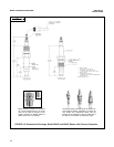
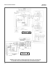
2.2.3 Quik-Loc Mounting for Model 397. The Quik-
Loc mounting is used with the Model 397 TUpH sen-
sor only.
SAFETY WARNING
It is recommended that a thermometer,
drain valve to relieve pressure and
pres-sure gauge be inserted near the
Quik-Loc assembly (see Figure 2-5).
WARNING
Once the Quik-Loc unit is installed the oper-
ator should wait for the process to cool to a
safe temperature, use the pressure drain
valve to relieve all process pressure and
observe the pressure on the pressure gauge
for proper removal of the sensor without
spray or bodily injury. The Quik-Loc kit used
with the 397 TUpH sensor is not recom-
mended for use with hazardous, corrosive,
or strong oxidizing chemicals due to a risk of
spray or bodily injury.
MODEL 396/396VP/397/398/398VP SECTION 2.0
INSTALLATION
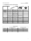
2.1 UNPACKING AND INSPECTION. Inspect the out-
side of the carton for any damage. If damage is detect-
ed, contact the carrier immediately. Inspect the instru-
ment and hardware. Make sure all the items in the pack-
ing list are present and in good condition. Notify the fac-
tory if any part is missing. If the sensor appears to be in
satisfactory condition, proceed to Section 2.2, Mounting.
NOTE
Save the original packing cartons and mate-
rials as most carriers require proof of dam-
age due to mishandling, etc. Also, if it is nec-
essary to return the instrument to the facto-
ry, you must pack the instrument in the same
manner as it was received. Refer to Section
6 for return instructions. If the sensor is to be
stored, the vinyl boot should be filled with pH
buffer solution and replaced on sensor tip
until ready to use.
WARNING
Glass electrode must be wetted at all times (in
storage and in line) to maximize sensor life.
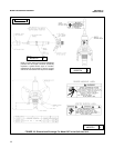
2.2 MOUNTING. Each sensor has been designed to
be located in industrial process environments.
Temperature and pressure limitations must not
be exceeded at any time. A caution or warning label
regarding this matter is attached to each sensor. For
insertion, transfer the label as shown on label instruc-
tions. See Figure 2-2. For submersion applications, first
note limits then remove and discard label.
NOTE
Before mounting the sensor, shake down
the sensor to remove any air bubbles that
may be present at the tip of the pH glass
bulb. In most cases, the pH sensor can sim-
ply be installed as shipped and readings
with an accuracy of ±0.6 pH may be
obtained. To obtain greater accuracy or to
verify proper operation, the sensor must be
calibrated as a loop with its compatible ana-
lyzer or transmitter.
SECTION 2.0
INSTALLATION