


10
MODEL 399VP pH/ORP SENSOR SECTION 3.0
WIRING
SECTION 3.0.
WIRING
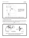
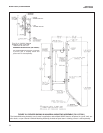
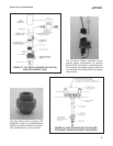
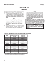
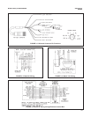
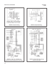
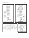
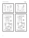
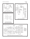
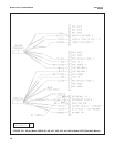
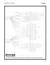
Figures 3-2 thru 3-23 provide the diagrams for wiring
the 399VP sensor to various analyzer/transmitters.
1. If the cable needs to be extended, use a high quali-
ty cable available from Rosemount Analytical. Refer
to Figures 3-2 through 3-23 for the appropriate junc-
tion box part number and the corresponding wiring
details.
NOTE
If the extension cable is too long, either loop up
the excess cable or cut and terminate each
conductor neatly. Make sure that the overall
(outermost) drain wire is not shorted out
with either of the two inner drain wires
(shields).
2. Signal cable should be run in a dedicated conduit
(preferably an earth grounded metallic conduit)
and should be kept away from AC power lines.
NOTE
When extending the mV signal from the sensor
through a remote junction box to the analyzer,
the outer braid of the extension cable to the
instrument must be terminated at earth ground
or by using an appropriate metal cable gland
fitting that provides a secure connection to the
instrument cable.
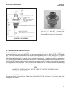
The Model 399VP is used with a Variopol coax cable.
The cable should be handled carefully and kept dry and
free of corrosive chemicals at all times. Extreme care
should be used to prevent it from being twisted, dam-
aged or scraped by rough, sharp edges or surfaces.
DANGER
DO NOT CONNECT SENSOR CABLE TO
POWER LINES. SERIOUS INJURY MAY
RESULT.
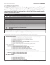
Model Remote Junction Extension
Box PN Cable PN
54 23555-00 9200273*
81 23555-00 9200273*
1003/1023 23309-03 9200000
1050/1060 23309-03 9200000
1054 23309-04 9200273*
1054A/B 23309-04 9200273*
1055 23555-00 9200273*
1181 23309-03 9200273*
2054 23309-04 9200273*
2081 23309-04 9200273*
3081/4081 23555-00 9200273*
SCL — —
2700 — —
TABLE 3-1. Remote Junction Box and Extension Cable Part Numbers
* Note that PN 9200273 is a raw cable. It can also be purchased with
wires already prepared (PN 23646-01) for quicker installation.