


MODEL 399VP pH/ORP TABLE OF CONTENTS
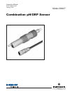
MODEL 399VP pH/ORP SENSOR
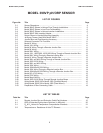
LIST OF FIGURES
Figure No. Title Page
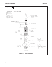
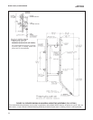
2-1 Sensor Dimensions........................................................................................... 4
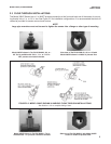
2-2 Model 399VP Shown in Various Flow-Through Installations............................. 5
2-3 Model 399VP Shown in Low Flow Cell Assembly ............................................. 6
2-4 Model 399VP Shown in Various Insertion Installations ..................................... 6
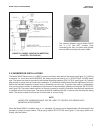
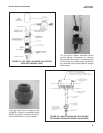
2-5 Model 399VP With Insertion Adapter ................................................................ 7
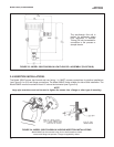
2-6 Sensor Shown in Handrail Mounting Assembly ................................................ 8
2-7 Jet Spray Cleaner Used With Model 399VP ..................................................... 9
2-8 Junction Box and Pipe Mounting Accessory ..................................................... 9
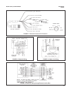
3-1 Wire and Connector Pin Functions ................................................................... 11
3-2 Model 81 Wiring ................................................................................................ 11
3-3 Model 1181 Wiring ............................................................................................ 11
3-4 Model 54 Wiring Through a Remote Junction Box............................................ 11
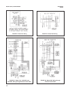
3-5 Model 54 Wiring ................................................................................................ 12
3-6 Model 2081 Wiring ............................................................................................ 12
3-7 Model 1181, 1050/1060, 1003/1023 Wiring Through a Remote Junction Box.. 12
3-8 Model 2081 Wiring Through a Remote Junction Box........................................ 12
3-9 Model 81 Wiring Through a Remote Junction Box............................................ 13
3-10 Model 3081 and 4081 Wiring Through a Remote Junction Box........................ 13
3-11 Model 1055-22-32 Wiring.................................................................................. 13
3-12 Model 3081 and 4081 Wiring ............................................................................ 13
3-13 Model 1054 Wiring ............................................................................................ 14
3-14 Model 1054A/B and 2054 Wiring ...................................................................... 14
3-15 Model 1054 Wiring Through a Remote Junction Box........................................ 14
3-16 Model 1054A/B and 2054 Wiring Through a Remote Junction Box.................. 14
3-17 Model SCL-(P/Q) Wiring ................................................................................... 15
3-18 Model 2700 Wiring ............................................................................................ 15
3-19 Model 54epH Wiring.......................................................................................... 15
3-20 Model 1055-22-32 Wiring Through Remote Junction Boxes ............................ 15
3-21 Wiring Model 399VP-09 to Model 1055 (Pipe/Wall Mount)............................... 16
3-22 Wiring Model 399VP-09 to Model 1055 (Panel Mount)..................................... 17
3-23 Preparation of Raw Connecting Cable.............................................................. 18
LIST OF TABLES
Table No. Title Page
3-1 Remote Junction Box and Extension Cable Part Numbers............................... 10
4-1 ORP of Saturated Quinhydrone Solutions (in Millivolts).................................... 20
5-1 R
o
& R
1
Values for Temperature Compensation Elements .............................. 21
5-2 Temperature vs. Resistance of Auto TC Element.............................................. 21
ii