


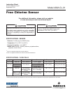
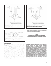
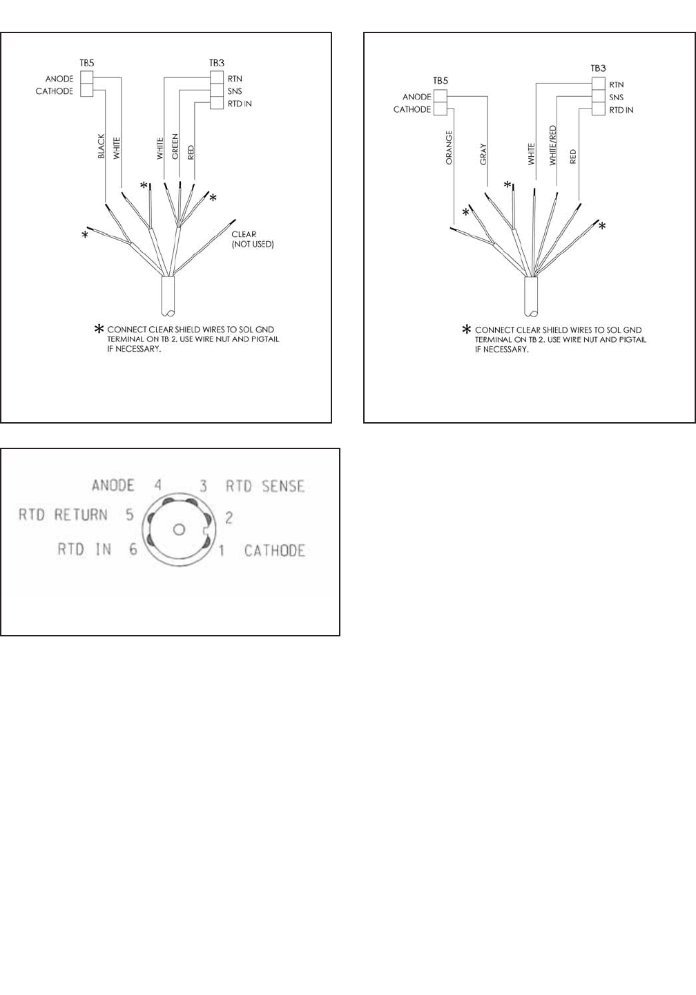
FIGURE 13. Wiring Sensor with Standard Cable to
Model 1066 Transmitter.
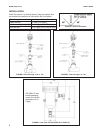
FIGURE 14. Wiring Sensor with Optimum EMI/RFI or
Variopol Cable to Model 1066 Transmitter.
CALIBRATION
Zero point: Even in the absence of free chlorine, the
499ACL-01 sensor generates a small signal called the
zero current. Failing to correct for the zero current can
introduce a bias, particularly if the chlorine concentra-
tion is small (<0.4 ppm). Zero the sensor when it is first
placed in service and every time the fill solution is
changed. To zero the sensor, place it in a cup of deion-
ized or bottled water to which a few pinches of table
salt have been added to increase the conductivity.
Once the sensor current has reached a stable low
value, which takes at least two hours, follow the ana-
lyzer prompts for zeroing the sensor. The zero current
should between -10 and +10 nA. For more information
refer to the analyzer manual.
Full Scale: Because stable dilute chlorine standards
are not available, the sensor must be calibrated
against the results of a laboratory test run on a grab
sample of the process liquid. Place the sensor in the
flow cell and adjust the sample flow to within the range
given in the table on page 2. Also, adjust the concen-
tration so that it is near the upper end of the operating
range. Once readings are stable, follow the analyzer
prompts to complete the calibration. Be sure taking the
sample does not alter flow to the sensor and test the
sample immediately after taking it. After calibration, go
to the diagnostics menu and check the sensitivity. It
should be between 200 and 450 nA/ppm. For more
information, refer to the analyzer manual.
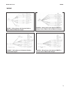
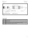
MODEL 499A CL-01 WIRING
5
When making connections through a junction box
(PN 23550-00), wire point-to-point.
NOTE:
Use a wire nut and pigtail (included) when
connecting several wires to the same terminal.
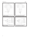
FIGURE 15. Pin Out Diagram for Model 499ACL-
VP Sensor (top view of connector end of sensor)