


www.easyheat.com
Heating cable control options and power
connection
For 120 Volt cables, the heating cable can simply be plugged
into a ground fault protected electrical receptacle.
For 240 Volt cables, the cable is designed to be directly
connected into an appropriate electrical outlet box supplied
by ground fault protected circuit. Since it will be necessary
to remove power from the cable from time to time, such
as in summer, always connect the cable to an appropriate
double-pole electrical switch. If the heating cable is the only
load on the circuit, the branch circuit breaker may be used to
disconnect power from the cable (switch is not necessary).
In addition, a remote thermostat similar to EasyHeat model
C3RC can be used for 120 Volt or 240 Volt cables to reduce
energy consumption and extend the life of the cable. Consult
your local EasyHeat supplier or representative for other control
options.
Testing the system
Once the installation is complete, apply power to the heating
cable; wait about one hour, and then turn on a water tap
supplied by the protected pipe and test the temperature of
the water. It should feel warm almost immediately as the water
heated by the cable ows through the pipe.
Operation. Energize the cable/control upon the arrival of cold
weather in the fall and de-energize the cable in late spring.
Maintenance
Check cable each year for any damage before energizing the
heating cable. Check any ground fault protection device for
proper operation. Check pipe insulation and replace any that
may be loose or damaged. Do not operate the cable if any
damage is found.
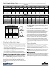
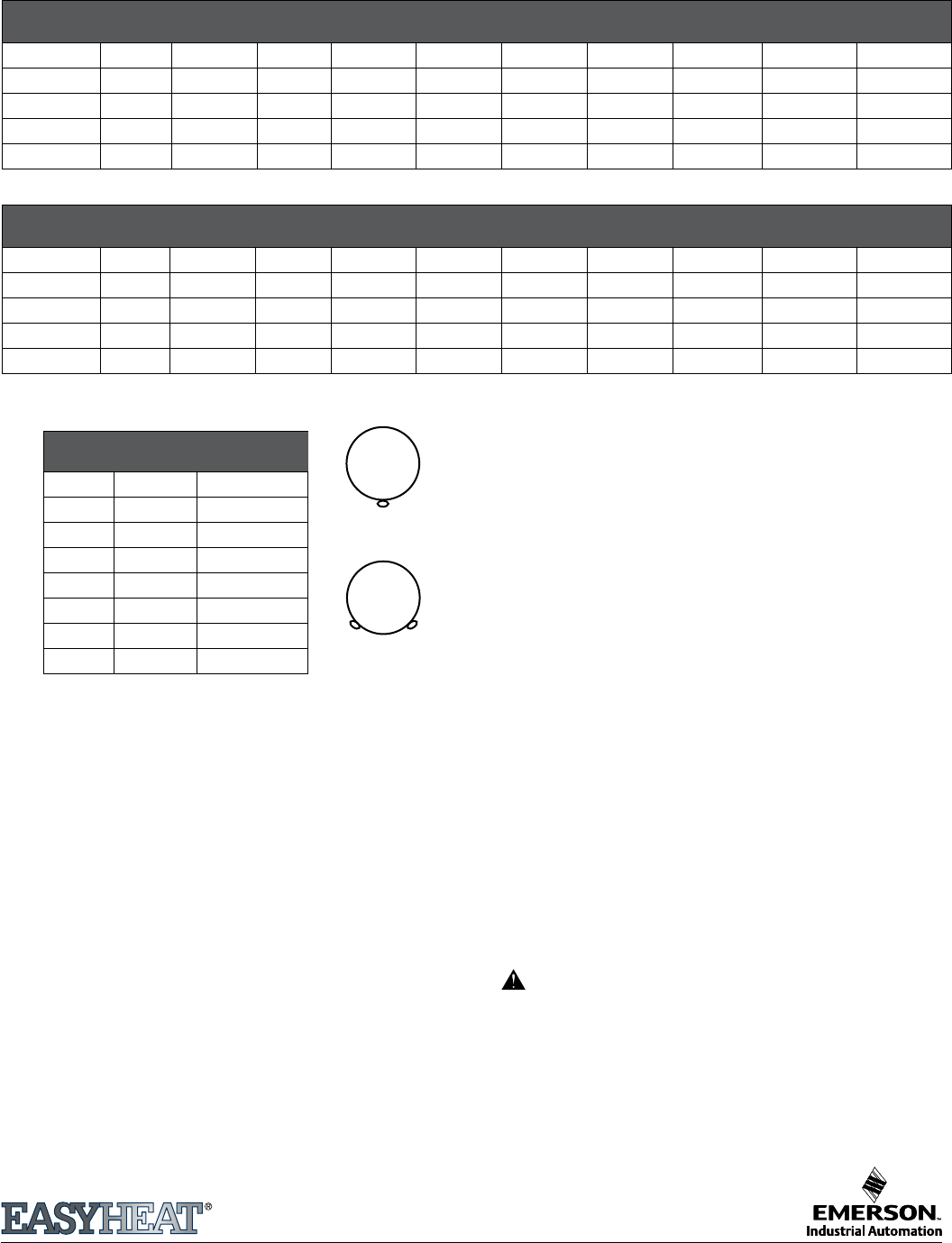
Cable Length Selection Chart
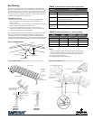
Attaching heating cable to pipes
Wrap EasyHeat HCA (optional Application Tape) or nylon cable ties
at 6" (15.24 cm) intervals to secure the heating cable to the pipe.
• If the heating cable is the same length as the pipe, run it straight
along the bottom of the pipe. If two cables are required, position
them in the 4 and 8 o’clock positions.
• If the cable selected is exactly double the pipe length, apply a
single trace of cable straight along the pipe all the way to the
end, and loop back, applying cable straight along the pipe all
the way back to the starting point.
• If the cable selected is somewhat less than double the pipe
length, spiral the cable evenly along the entire length of pipe.
Protecting the system with thermal insulation
Before insulating, ensure that there is no damage, such as nicks or
cuts on the heating cables. Immediately cover the pipe, cables,
connections, valves and spigots with 1/2" (12.7 mm) to 1" (25.4 mm)
thick berglass insulation or equivalent. Do not leave the cables
exposed. Use re-resistant materials such as berglass wrap. Make
sure the insulation is waterproofed (with polyethylene or other
vapor barriers) in areas where water may come in contact with the
insulation.
Ambient Temperature -20°F (-28.89°C), with 0.5" (12.7mm) Thick Fiberglass Insulation
METAL PIPE
Pipe Dia
3'
.91m
4'-6'
1.2m-1.83m
7'
2.13m
8'-12'
2.44-3.66m
13'-14'
3.96-4.27m
15'-18'
4.57-5.49m
19'- 25'
5.79-7.62m
26'-50'
7.92-15.24m
51'-75'
15.54-22.86m
76'-100'
21.16-30.48m
0.5" (12.7mm) A A B B C C E F G
1.0" (25.4 mm) A A A B B C C E F G
1.5" (38.1 mm) A A A B B C D E F G
2.0" (50.8 mm) A B B C C D E F G H
2.5" (63.5 mm) A B B C C D E F G H
PLASTIC PIPE
Pipe Dia
3'
.91m
4'-6'
1.2m-1.83m
7'
2.13m
8'-12'
2.44-3.66m
13'-14'
3.96-4.27m
15'-18'
4.57-5.49m
19'- 25'
5.79-7.62m
26'-50'
7.92-15.24m
51'-75'
15.54-22.86m
76'-100'
21.16-30.48m
0.5" (12.7mm) A B B C D D E F G
1.0" (25.4 mm) A A B C C D E E F G
1.5" (38.1 mm) A B C D D E E F F H
2.0" (50.8 mm) A B C E E E E F G H
2.5" (63.5 mm) A B C E E E F F G H
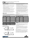
Single Cable
Double Cable
SELECTION CHART KEY
Model # # of Cables
A PSR (*)006 1 Cable
B PSR (*)012 1 Cable
C PSR (*)018 1 Cable
D PSR (*)024 1 Cable
E PSR (*)050 1 Cable
F PSR (*)075 1 Cable
G PSR (*)100 1 Cable
H PSR (*)100 2 Cable
Replace* with voltage code:
1 for 120V; 2 for 240V