


10
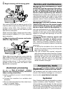
b) Router table for edge veneer
The "router table for edge veneer" (only in SET
scope of delivery) is designed for fl ush trim-
ming veneer overhang and profi le routing.
Notes:
The router table is tilted 1.5° so that the f
surface coating is not damaged during edge
routing. A router table with 0° inclination
angle for precise cuts is available as an
accessory.
5-1
5-2
1
2
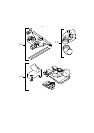
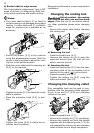
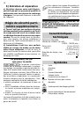
Secure the sensor [5-1] to the machine –
using the preassembled screws. Slide the
sensor in the long holes to adjust the rout-
ing tool to the perfect position.
Slide the router table onto the retaining pin –
[5-2] on the machine.
5-3
5-4
3
4
Tighten the screw [5-3] to clamp the router –
table in position.
Place the extraction hood [5-4] in posi- –
tion.
5-5
5
Tighten the screw [5-5] to clamp the ex- –
traction hood in position.
Removal is performed in reverse sequence to
installation.
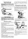
Changing the routing tool
Risk of accident - the routing
tool may be hot after use and has sharp
edges. Allow the tool to cool before chang-
ing. Wear protective gloves when changing
tools.
Remove the router table before changing –
the routing tool.
SW 19
6-2 6-3
6-1
1
2
3
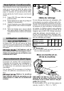
a) Removing the tool
Press the spindle lock [6-1]. –
Unscrew the locking nut [6-2] using the –
open-end wrench (size 19) until you are
able to remove the tool.
b) Inserting the tool
Insert the routing tool [6-3] into the open –
clamping collet as far as possible, but at
least up to the mark (
) on the shank.
Press the spindle lock [6-1]. –
Tighten the locking nut [6-2] using the –
open-end wrench (size 19).
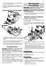
Changing the clamping collet
Only compatible tools can be used in com-
bination with the clamping collets supplied.
8 mm, 6 mm and 1/4" (6.35 mm) clamping
collets can be used.
7-2 7-3
7-1
1
2
3
Press the spindle lock [7-1]. –
Unscrew the locking nut [7-2] completely. –
Remove the locking nut from the spindle –
together with the clamping collet [7-3]. Do
not separate the locking nut and clamping
collet as these form a single component.