


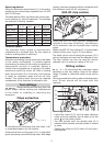

5
Speed regulation:
Using the electronic speed control (1.1) the motor
speed can be continuously adjusted from 10 000
and 23 000 rpm.
The table below offers a guide to the correct elec-
tronic setting for various materials. The settings
are naturally infi nitely variable.
Material
Cutter diameter [mm] Cutter
material
3-14 15-25 26-35
Hard wood 6-4 5-3 3-1 HW/HSS
Soft wood 6-5 6-3 4-1 HSS/HW
Panels 6-5 6-3 4-2 HW
Plastic 6-4 5-3 2-1 HW
Aluminium 3-1 2-1 1 HSS/HW
Plasterboard 2-1 1 1 HW
Constant speed:
The selected motor speed is electronically
maintained to a constant level. By this means a
uniform cutting speed is achieved.
Temperature protection:
Extreme overloading during continuous use leads
to the motor overheating. To protect against
overheating (burnout of the motor) an electronic
temperature monitor is installed. Before a
critical motor temperature is reached, the safety
electronics switch the motor off. After a cooling
down time of about 3 to 5 minutes, the machine
is ready for operation again and can be fully
loaded. The cooling down time can be reduced
considerably if the machine is allowed to idle.
Tool settings
Always disconnect the plug from the
power supply before making any adjustments
to the router or installing or removing any
accessory!
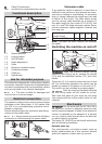
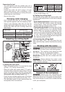
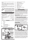
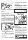
Chips extraction
4.1
4.2
A connection for extracting dust and chips (1.6)
is a standard feature on the routers.
At the same time a chip guard (4.1) on the pallel
guide (accessory) prevents fl ying chips. With edge
routing, the best extraction effect is obtained with
the extractor hood AH-OF (accessory).
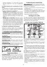
KSF-OF chip catcher
5.1
5.2
Using the KSF-OF chip catcher (sometimes
included in the scope of delivery), the effi ciency
of the extraction can be increased when routing
edges.
Fasten the KSF-OF chip catcher (5.1) to the platen
instead of the cover ring (4.2) from below.
The hood can be cut off along the grooves (5.2)
using a hacksaw and can thus be reduced in size.
The chip catcher can then be used for interior
radiuses up to a minimum radius of 40 mm.
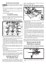
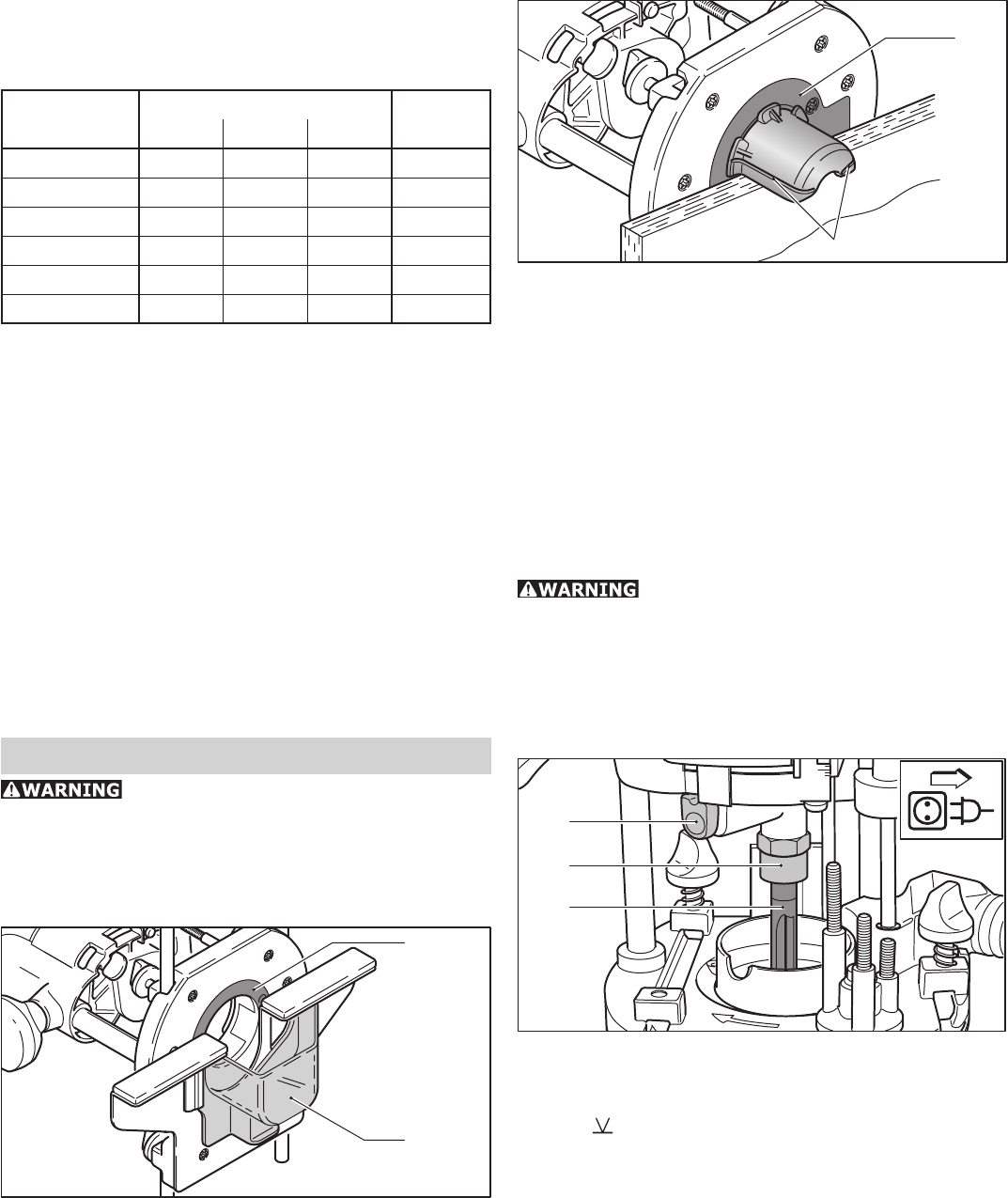
Milling cutters
Do not exceed the maximum speed
specifi ed on the tool and/or keep to the speed
range. Cracked or distorted cutters must not be
used.
We recommend that milling cutters with diameters
over 30 mm should not be used with this
machine.
6.2
6.3
6.1
Inserting the tool
- Insert the router (6.3) into the open clamping
collet as far as possible, but at least up to the
mark
on the router shank.
- Turn the spindle until the spindle stop (6.1)
catches when pressed and the spindle is locked
in place.
- Tighten the collet nut (6.2) with a 19 mm open-
end spanner.