


6
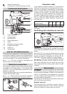
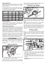
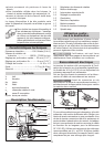
Removing the tool
- Turn the spindle until the spindle stop (6.1)
catches when pressed and the spindle is locked
in place.
- Loosen the collet nut (6.2) using a 19 mm
open-ended spanner until a resistance is felt.
Overcome this resistance by turning the open-
ended spanner even further.
- Remove the cutter.
Clamping collet changing
- Fully unscrew the collet nut (6.2) and remove
from spindle together with the clamping collet.
- Insert a new clamping collet with nut into the
spindle and slightly tighten the collet nut. Do not
tighten the collet nut until a milling cutter has
been fi tted!
Cutter shank Clamping collet
ØOrder-No.
Ø 6 mm 6 mm 488 764
Ø 6,35 mm (1/4") 6,35 mm 488 765
Ø 8 mm 8 mm 488 763
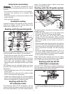
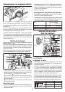
Adjusting the milling depth
7.8
7.3
7.2
7.1
7.4
7.5
7.6
7.7
The milling depth is adjusted in three stages:
a) Setting the zero point
- Open the clamping lever (7.4) so that the stop
cylinder (7.5) can be moved freely.
- Place the router with router table (7.7) onto a
smooth surface. Open the rotary knob (7.8) and
press the machine down until the milling cutter
rests on the base. Clamp the machine tight in
this position with the rotary knob (7.5).
- Press the stop cylinder against one of the three
sensing stops of the pivoted turret stop (7.6).
- The individual height of each sensing stop can
be adjusted with a screwdriver.
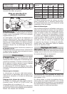
Sensing stop min. height max. height
A
B
C
A 38 mm 44 mm
B 44 mm 54 mm
C 54 mm 67 mm
- Push the pointer (7.1) down so that it shows
0 mm on the scale (7.3).
b) Setting the milling depth
The desired milling depth can be set either with
the quick depth adjustment or with the fi ne depth
adjustment.
- Quick depth adjustment: Pull the stop cylinder
(7.5) up until the pointer shows the desired
milling depth. Clamp the stop cylinder in this
position with the clamping lever (7.4).
- Fine depth adjustment: Lock the stop cylinder
with the clamping lever (7.4). Set the desired
milling depth by turning the adjusting wheel
(7.2) in. Turn the adjusting wheel to the next
mark on the scale to adjust the milling depth by
0.1 mm. One full turn adjusts the milling depth
by 1 mm. The maximum adjustment range with
the adjusting wheel is 8 mm.
c) Increasing the milling depth
Open the rotary knob (7.8) and press the tool
down until the stop cylinder touches the sensing
stops.
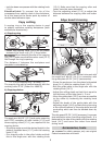
Working with the router
Always secure the workpiece in such a
manner that it cannot move while being sawed.
The machine must always be held
with both hands by the designated handles.
Always switch the router on fi rst
before bringing the tool into contact with the
workpiece!
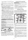
Always advance the router in the
same direction as the cutting direction of the
cutter (counter-routing)!
8
Support of the workpieces
Ensure that your workpieces are
securely fi xed and cannot move during routing.
Otherwise, there is an increased risk of accident.
Use screw clamps or some other suitable devices
to fi x your workpiece.