


6
Electrical connec-
tion and operation
The supply voltage must comply with the volt-
age given on the ratings plate.
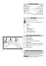
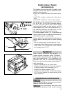
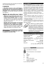
The switch (1.2) is used as an on/off switch.
For your safety this is equipped with a switch-
on interlock (1.1 ). In order to run the planer
the switch-on interlock must fi rst be pressed
and then the switch.
Extension cable
If an extension cable is required, it must have
a suffi cient cross-section so as to prevent an
excessive drop in voltage or overheating. An
excessive drop in voltage reduces the output
and can lead to failure of the motor. The table
shows the correct size to use, depending on
cord length and tool‘s ampere rating. Use only
U.L. and CSA listed extension cables. Never
use two extension cables together. Instead,
use one long one.
Total Extension Cord
Lenght (feed)
25 50 100 150
Cord size (AWG) 18 16 14 12
Note: The lower the A.W.G. number, the
stronger the cable.
Electronic control
The devices are fi tted with a full-wave elec-
tronic control with the following functions:
Smooth start-up
The electronically-controlled smooth start-
up ensures that the machine starts without
jolts.
Idling speed
The electronic circuit limits the idling speed.
This means that the noise level also remains
low during idling.
Constant speed
The speed of the planer shaft is electronically
regulated to a constant value, thus also pro-
viding a constant cutting speed under load.
Temperature protection
Extreme overload in continuous running will
cause the motor to overheat. An electronic