


5
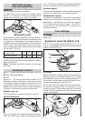
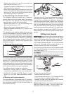
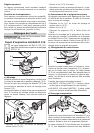
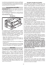
– Release the screw (4.1) on the clamping lever
and remove the lever (4.2).
– Tighten the square-headed screw (4.3) by hand
until a tension is obtained.
– Re-fi t the clamping lever and secure it with the
screw. The optimum clamping force can be de-
termined by closing the clamping lever before
the clamping screw is tightened.
b) Repositioning the rotatable handle
The rotatable additional handle can, if required,
also be fi tted to the right-hand side of the extrac-
tor hood. For this purpose, the handle and the
clamping lever should be interchanged.
– Release the screw (4.1) on the clamping lever
and remove the lever (4.2).
– Remove the square-headed screw (4.3).
– Detach the additional handle (4.5), using a 6 mm
A/F Allen key.
The clamping lever and the additional handle can
now be interchanged. Fitting is carried out in the
reverse of the above sequence. The locking nut
(4.4) can be used to vary the turning resistance
of the rotatable additional handle by tightening
the nut against the housing, using a 13 mm A/F
open-ended wrench, before fully tightening the
additional handle.
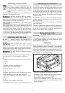
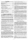
c) Replacing the brush insert
5.1
5.2
In order to replace this, press out the brush insert
by inserting a screwdriver through the square ap-
ertures (5.1). Insert the new brush strip (5.2) into
the groove, slightly bend this to obtain the correct
radius and press in fi rmly until the brush strip is in
contact with the base of the hood. The inclination
of the brush bristles must point outwards.
Two different brush inserts are available:
• AH-RAS D 115 Poly (484727): Pack of 2 polyam-
ide brushes (replacement for worn origi-nals)
• AH-RAS D 115 metal (484728): Pack of 1 metal
brush (for use with spark-generating materi-
als)
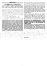
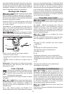
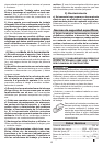
d) Sanding with dust extraction
For dust extraction, the suction hose (27 mm dia.)
of a Festool dust extractor should be inserted into
the connection socket (6.3) at the end of the ro-
tary sander housing.
6.36.1 6.2
The brush ring (6.2) can be adjusted by means of
the additional rotatable handle (6.1). This makes
it possi-ble to achieve an optimum setting for
the working position used. Always turn the brush
ring into the direc-tion of travel of the sanding
dust. A considerable quantity of air-borne sparks
are generated during the sanding of metals and
other spark-generating materials. For safety rea-
sons, therefore, a spark-trap (484733) must be
fi tted between the extractor hood and the rotary
sander.
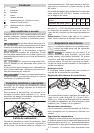
Fitting tool inserts
Use only tool inserts whose maximum
permissible speed is at least equal to the speed
given on the rating plate of the rotary sander. This
is the case with all original Festool accessories.
The Stickfi x sanding pads STF D 115 are provided
with an M 14 thread which enables these to be
screwed directly onto the drive spindle.
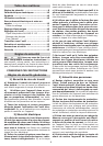
It is normally possible to unscrew the sanding pad
(7.3) by hand from the drive spindle after pressing
the spindle stop (7.1).
Actuate the spindle stop only when the
drive spindle is stationary. Do not switch on the
motor when the spindle stop is pressed in.
7.1
7.2
7.3
7.4
In case the pad should seize:
– Remove the brush insert.
– Insert the special spanner (7.4) through the slot
(7.2) and place on spanner fl ats of tool.
– Release the tool with the spindle stop pressed
by turning the special spanner.
Please note: Always screw the sanding pad onto
the drive spindle by hand. This will make it con-
siderably easier to remove it subsequently.