


NOTE ON CONNECTING AIR LINE TUBING
Cut the air line tubing as squarely as possible. To connect the air
line tubing to the fittings push the tubing into the fittings as far as
possible. If for any reason the tubing must be removed the collar of
the fitting can be pushed toward the body of the fitting and the tubing
can be removed. Make sure the air helper springs are deflated. To
reassemble make sure the tubing is cut squarely and push back into the
fitting.
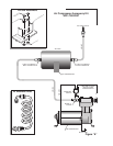
STEP 1
Locate the brass "T" fittings as shown in Figure "A". This fitting
has a preapplied thread sealant on the male threads. No additional
sealant is required.
Install the male threaded end into the compressor head as shown
in Figure "A". Tighten finger tight PLUS 3 1/2 turns. Next get the
pressure switch from your hardware pack. Screw the pressure switch
into the "T" fitting as shown in Figure "A". Then attach the positive
(RED) wire from the compressor to one of the terminals on the pressure
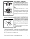
switch. Install the rubber isolators and brass sleeves to the compressor
feet (see Figure "B").
STEP 2
Select a convenient location for mounting the compressor. This
location should provide ample air flow and be protected from most airborne debris. The surface should be rigid to
support the unit. Some examples might include under the hood on a fender well, or in a vented storage compartment.
Using the template supplied, mark and drill three 1/4" holes. It is
recommended that burrs be removed from the holes so as not to damage
the rubber isolator. Mount the compressor using the #10 pan head
machine screws and #10 flat washers located in your hardware pack.
Assembly of the flat washers, machine screws, and lock nut are shown
in Figure "B". Proper mounting of this compressor will provide
maximum isolation. Figure "B" shows the before and after condition
of the rubber isolator. The screw and nut should be tightened only
enough to bottom out on the brass insert. DO NOT OVER TIGHTEN
further tightening will crush the insert and isolator and reduce vibration
isolation.
Attach the black wire from the compressor to a convenient ground
source on the vehicle. Most any metal connection point common to
the vehicle frame should be suitable.
STEP 3
Get the air tank and mount two 1/4" NPT male connectors into the air tank ports (see Figure "A").
Select a location for mounting the air tank. This location should be protected to prevent damage from flying rocks
or debris. Mark and drill two 7/16" holes 2-1/2" apart. Bolt the tank in place using the 3/8"-16 x 1-1/2" hex bolts,
washers and lock nuts provided. Be sure clear access is provided to the two air ports. (SEE CAUTION NOTE).
CAUTION:
The air tank supplied with this kit should be protected. Dents or punctures could cause air leaks, personal
injury or property damage. Do not exceed 120 psi in the tank.
STEP 4
Measure a length of air line tubing to go from the compressor to the tank and cut as squarely as possible. A ragged
or angled cut can cause a leak in the system. Do not fold or kink the air line tubing.
Figure "B"
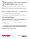
AIR LINE
PUSH-TO-CONNECT
INFLATION VALVE
FLAT WASHER
HEX NUT
VALVE CAP
BODY OF
VEHICLE
Figure "C"
BRASS SLEEVE COMPRESSOR
FOOT
RUBBER
ISOLATOR
LOCK NUT
FLAT WASHER
COMPRESSOR
FOOT
RUBBER
ISOLATOR
VEHICLE
MOUNTING
SURFACE
FLAT
WASHER
#10 PAN
HEAD
SCREW
BRASS
SLEEVE