


STEP 5
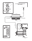
Select a point on your vehicle for the inflation valve. This should be a rigid surface, easily accessible and convenient
(examples might be a wheel well or bumper). Drill a 5/16" hole and install the inflation valve as shown in Figure
"C". Tighten the inflation valve securely and replace the cap.
NOTE: The cap should always be replaced to protect the inflation valve from dirt and debris.
STEP 6
Measure a length of remaining air line tubing to run from the tank to the inflation valve. Cut as squarely as possible
and install according to previous directions.
NOTE: We have provided 18 feet of air line tubing in this kit. Should your installation require more, or your
tubing becomes damaged, you should use 1/4" DOT approved nylon air brake tubing. This is available at most truck
parts dealers.
STEP 7
Get the red wire supplied in your hardware pack. This wire has attached to one end a 1/4" spade connector. Attach
this connector to the remaining stud on the compressor pressure switch. The other end of the wire is to be attached
to a positive 12 Volt D.C. supply capable of handling 20 amps. It is recommended that the connection be made to
an ignition contolled circuit. This method of connection will provide power to the compressor only when the key
is on. Consult your dealer or vehicle owners manual for proper fuse box connection.
Should you desire a circuit which is not ignition switch controlled a switch should be placed in the system. Make
sure the automotive switch you purchase is capable of 20 amps minimum. Turning the switch off when th compressor
is not needed will prevent the compressor from operating periodically and draining the battery. Consult you dealer
or vehicle owners manual for wiring diagrams.
NOTE: Should additional wire be necessary, use 16 gage multistrand wire.
YOU ARE NOW READY TO TEST THE SYSTEM
Turn on the ignition. The air compressor will run for a short time to build up pressure in the tank. Once this air
pressure reaches approximately 120 psi in the air tank, the pressure switch will turn the compressor off. It will not
restart until the pressure in the tank drops below 90 psi.
USING YOUR RIDE-RITE AIR COMPRESSOR ACCESSORY KIT
Your system is now ready to use. With the coiled tubing provided, attach the end with the screw style fitting to
the inflation valve. You can now use the air chuck on the opposite end to inflate Ride-Rite air helper springs, tires,
air shocks and many other items.
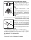
FILTER MAINTENANCE PROCEDURE
It is recommended that the air compressor filter be inspected periodically. The frequency that the inspection
should occur depends on how often the compressor is being used. The air compressor filter is located on the head
of the compressor opposite the "Tee" air fitting. If the filter is sufficiently clogged it will require replacement. A
used filter should not be cleaned or reused. Remove the felt filter media from the inlet port. A replacement filter
is supplied with your kit. Clean residual glue from the inside of the air port on the compressor. Apply glue to the
circumference of the replacement filter and install in the inlet port.
FIRESTONE INDUSTRIAL PRODUCTS
12650 HAMILTON CROSSING BOULEVARD
CARMEL, IN 46032
www.ride-rite.com
TM
R R