


SK-TSC-1125S User Guide
© Fujitsu Microelectronics Europe GmbH - 11 -
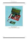
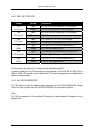
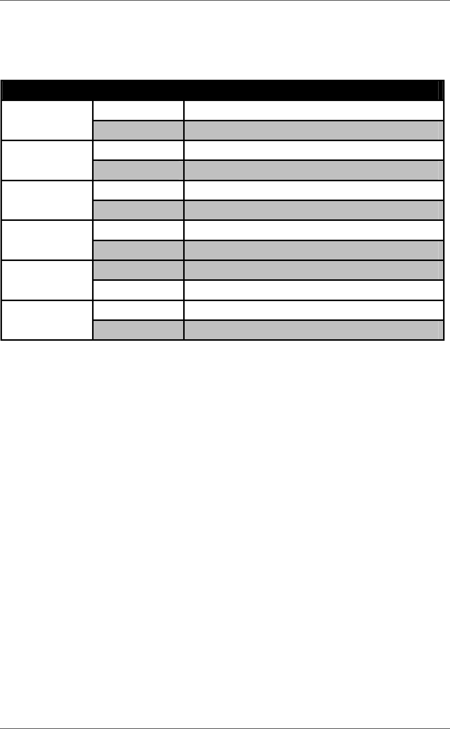
2.4.2 ADA-16FX-TSC-LCD
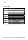
Jumper Setting Description
Open I2C SCL line not connected to Pull-up resistor
JP2
(SCL pull-up)
Closed I2C SCL line connected to Pull-up resistor
Open I2C SDA line not connected to Pull-up resistor
JP3
(SDA pull-up)
Closed I2C SDA line connected to Pull-up resistor
Open TSC Reset Pin (X1 Pin 8) not connected
JP3
(TSC Reset)
Closed TSC Reset Pin connected to MCU pin 17 (P04_3)
Open TSC SDA (X1 Pin 2) not connected to MCU JP4
(SDA)
Closed TSC SDA connected to MCU
Open LCD Backlight not connected or only via R4/R5 JP5
(LCD Backlight)
Closed LCD Backlight directly connected to VCC
Open TSC SCL (X1 Pin 1) not connected to MCU JP6
(SCL)
Closed TSC SCL connected to MCU
The contrast for the (optional) LC display can be adjusted using RP1.
A resistor suitable for the LCD backlight can be soldered on the PCB (R4 for 0805, R5 for
0805 or 1206). JP5 should only be closed if the LCD itself is equipped with a suitable series
resistor for the backlight.
2.4.3 SK-16FX-EUROSCOPE
The TSC starter kit uses the default jumper settings of the SK-16FX-EUROSCOPE. Please
refer to the user manual of the SK-16FX-EUROSCOPE for configuration options.
Note:
The TSC can operate at 3.3V as well as 5V (default), but most standard LC displays will only
operate at 5V.