


8
1.8 EVAPORATIVE EMISSIONS
INFORMATION
This generator is subject to evaporative emission standards which
have been implemented by the California Air Resource Board
(CARB) and the Environmental Protection Agency (EPA). If this
generator is offered for sale in the state of California, it must be
covered by a CARB evaporative Executive Order. If this generator
is offered for sale to the final consumer in any other state, certified
low-permeation fuel line must be used to supply fuel to the genera-
tor as required by EPA.
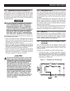
Anyone who installs or configures a fuel system to supply this
generator with gasoline is required to comply with all applicable
evaporative emission regulations. If this generator is configured
such that it shares the primary fuel system of a vehicle in which it
is installed, reduced certification requirements may apply. See the
CARB guidance document MAC 05-05, located at http://www.arb.
ca.gov/msprog/macs/mac0505/mac0505.pdf for further details. If
this generator is installed such that it uses a dedicated fuel system,
detailed evaporative emission requirements apply; contact a repu-
table fuel system manufacturer to purchase a complete fuel sys-
tem certified for use with this generator, or consult the California
Code of Regulations if you wish to obtain certification on your
own. See the installation instructions in this manual for connecting
fuel system vapor lines to the engine.
This generator is not legal for sale in the state of California unless
all CARB evaporative emission requirements are adhered to, and
is not legal for sale in any other state unless certified low-per-
meation fuel line is used to supply the generator with gasoline.
Contact the California Air Resource Board or the Environmental
protection agency for further information. CARB regulations can
be found in 13 CCR §§2750 – 2773; EPA regulations can be
found in 40 CFR Part 90.
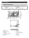
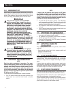
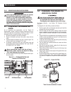
2.1 GENERATOR CONTROL PANEL
The following features are mounted on the generator control panel
(Figure 2.1):
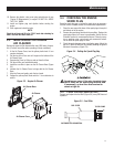
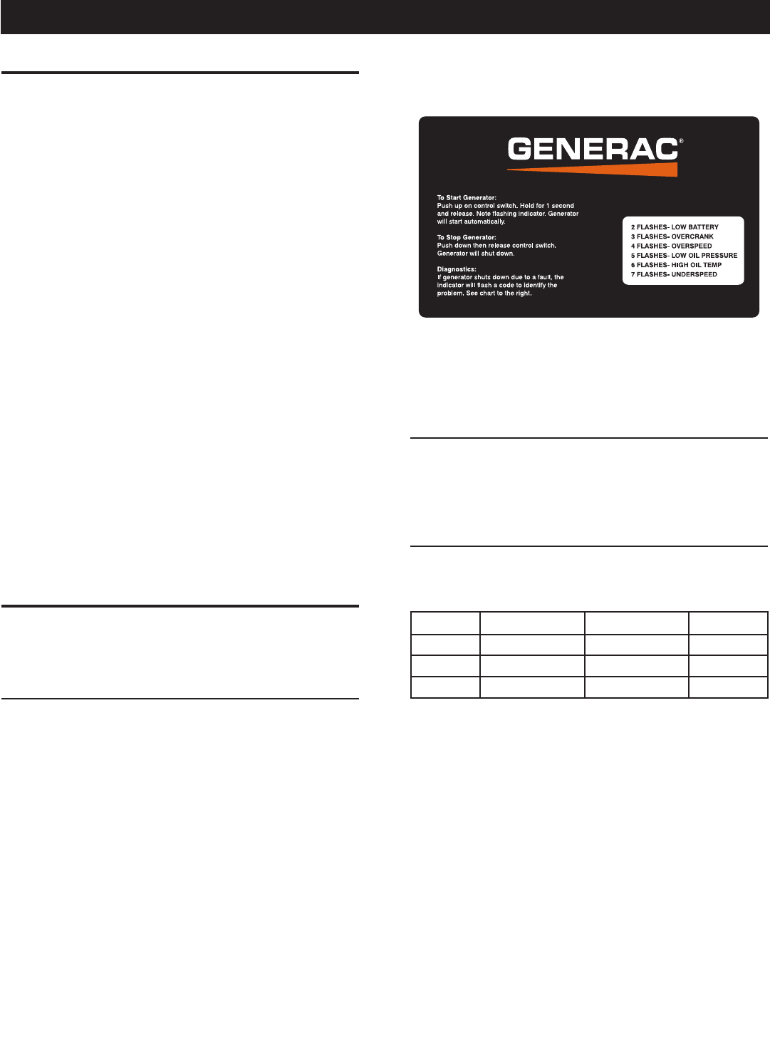
2.1.1 START/STOP SWITCH
This generator is started with a "One Touch" starting sequence.
Push up on the top half of the momentary switch. Hold for one
(1) second and release. Note flashing indicator light on the switch.
Fuel pump engages automatically for a three (3) to five (5) second
delay before starter motor cranks the engine for 16 seconds or
until the engine starts. If the engine does not start, the starter
will cool for seven (7) seconds and crank the engine again for 16
seconds. If the engine does not start, the starter will cool for seven
(7) seconds before cranking for seven (7) seconds to a maximum
cycle total of 90 seconds. Once started, the light on the switch
stays on continuously. If the generator does not start at the end
of the start sequence, a fault code will flash on the switch (see
Diagnostics).
The switch center position is the RUN position.
To stop a running engine, press momentarily the bottom half of the
switch to kill the ignition.
Figure 2.1 – Typical Control Panel
The switch center position is the RUN position.
To stop a running engine, press momentarily the bottom half of the
switch to kill the ignition.
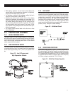
2.1.2 7.5 AMP FUSE
The fuse protects the engine’s DC control circuit against electrical
overload. If the fuse element has melted open due to overloading,
the engine cannot be cranked. If the fuse must be replaced, use
only an identical 7.5 amp replacement fuse.
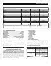
2.1.3 LINE BREAKERS
Protects generator’s AC output circuit against overload, i.e., pre-
vents unit from exceeding wattage/amperage capacity. The circuit
breaker ratings are as follows:
Model Cir. Breaker 1 Cir. Breaker 2 240 Volt
RV45 30A N/A N/A
RV55 20A 30A 25A 2P
RV65 30A 30A 30A 2P
NOTE:
If this generator has been reconnected for dual voltage AC out-
put (120/240 volts), install line breakers having an amperage
rating equal to that stated in the preceding chart. The replace-
ment line breakers consist of two separate breakers with a
connecting piece between the breaker handles (so that both
breakers will operate at the same time). If the unit is recon-
nected for dual voltage, it is no longer RVIA listed.
Operation