


Setting up
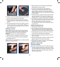
Multi position front handle
Screw the multi position front
handle (9) into the most suitable
mounting point (6) (left side, right
side or at the top) to suit the task
on hand.
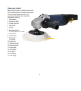
Variable Speed
The POL1450M is fitted with
a variable speed dial (3) that
allows you to adjust the speed to
suit the application and material.
The tool operates between the
speeds of
1500 RPM – 6500 RPM, the
higher the number on the
variable speed dial, the higher
the speed. For polishing
and buffing applications it is recommended that a lower
speed (1500 RPM) is used. For sanding applications it is
recommended that a medium speed (3500 RPM) is used to
provide efficient material removal, for grinding applications
the maximum speed (6500 RPM) should be selected.
WARNING. Do not operate the machine with a polishing
bonnet attached above 1500 RPM (Position 1 on the
variable speed dial).
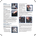
Operation in grinder mode
Fitting the grinding disc
Switch off the tool and disconnect it from the power supply.
WARNING. The guard must
always be attached and secured
to the tool during angle grinding
applications.
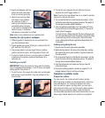
1. Fit the guard (15) onto the
spindle collar and rotate to
the required working position.
The closed side of the guard
must always be facing the operator.
2. Insert the guard securing
screw and tighten using
the matching nut. Use the
supplied Allen key to securely
tighten the screw.
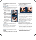
3. Place the inner flange (16)
onto the spindle making sure it
fits securely.
4. Ensure that the non-threaded
inner flange is on the spindle
and located correctly. The two machined flat sections on
the inner flange must face the angle grinder and locate in
the matching positions on the spindle.
5. Place the grinding or cutting disc on top of the inner
flange ensuring the bore fits into the raised centre section
of the flange.
6. Place the outer flange (17) over the spindle. For grinding
and cutting discs which are 5mm or thicker, fit the outer
locking flange (17) with the raised centre section inwards
towards the wheel. This helps to locate the disc on the
flanges.
7. For grinding and cutting discs which are less than 5mm
in thickness, fit the outer locking flange with the raised
centre section facing outwards, away from the disc.
8. Failure to fit the outer flange correctly as detailed above
will result in the outer flange tightening on the inner
flange but not clamping the disc.
9