


8
B
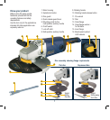
Setting up
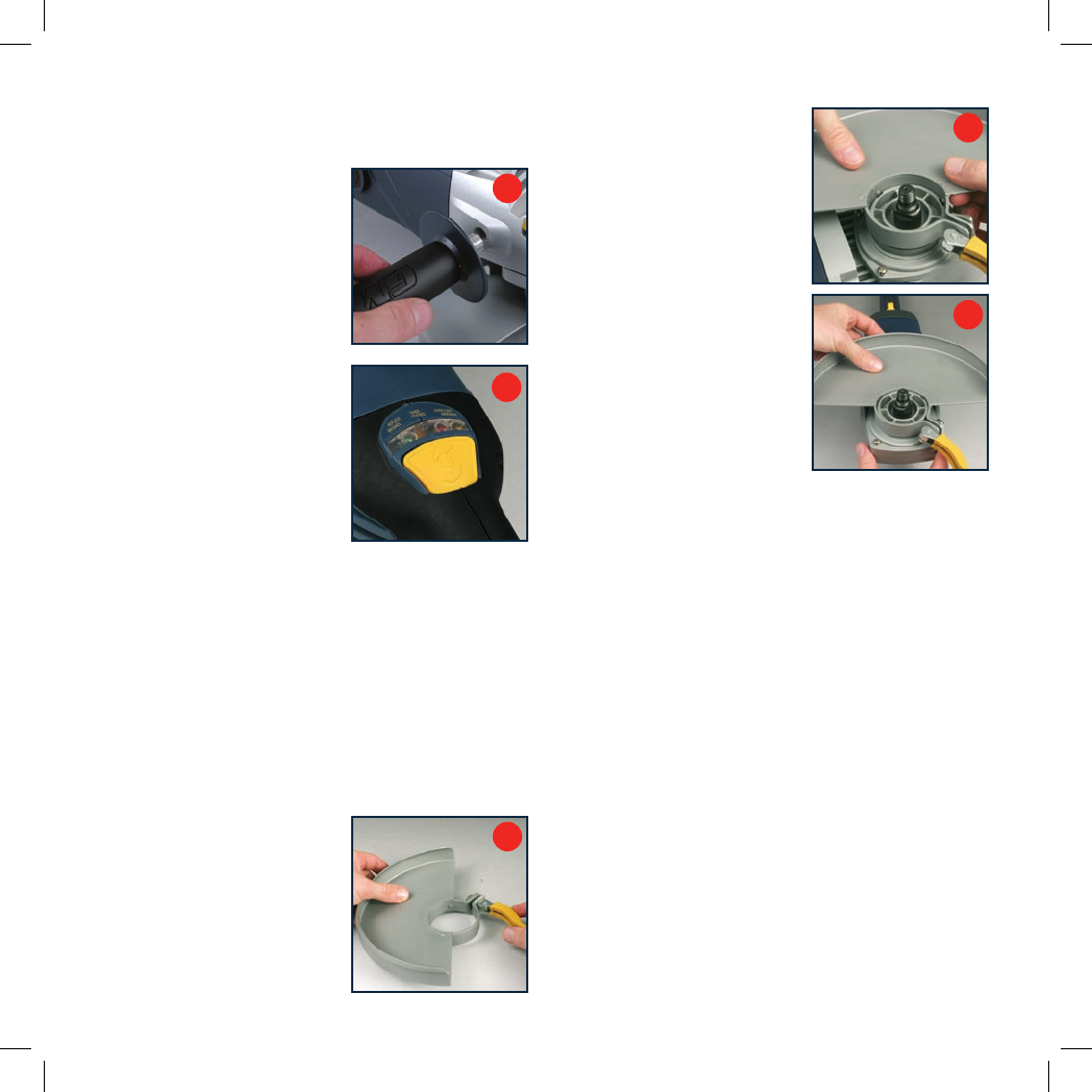
Multi-position auxiliary handle
1. Screw the multi-position
auxiliary handle (8) into the
most suitable mounting point
(5) (top, left side or right side)
to suit the planned operation.
(Fig. A)
2. Press the rotating handle
release button (10) and turn
the rotating handle (9) to suit
the planned operation. (Fig. B)
NOTE. The rear handle (9) can
be rotated to the left or right. It
must be “locked” into one of the
three preset positions: central,
90° to the left or 90° to the
right. It must not be used at any
position in between these three
preset positions as it might rotate
during use and create a hazard.
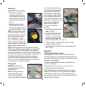
NOTE. Grinding operations normally require the angle
grinder to be held with the grinding disc at an angle of 20°
to 30° between the tool and the plane of the workpiece
whilst cutting operations normally require the angle grinder
to held with the cutting disc at right angles to the workpiece.
Take the time to find the best combination of auxiliary
handle and rotating handle positions to suit the task on
hand. It can make a considerable difference to the levels
of convenience and safety of operation.
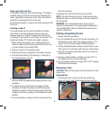
Disc guard
WARNING. Switch off the
grinder and disconnect it from
the power point.
NOTE. Grinding operations
normally require the angle
grinder to be held with the
grinding disc parallel to the plane
of the workpiece whilst cutting
operations normally require the
angle grinder to be held with
the cutting disc at right angles
to the workpiece. Take the time
to find the best combination of
front handle and slimline handle
positions to suit the task on hand.
It can make a considerable
difference to the levels of
convenience and safety of
operation.
1. Open the quick release guard
lever (4). (Fig. C)
2. Position the two lugs on the
inside of the central guard
ring in the vertical slot in the
spindle cover and press the
guard onto the spindle cover. (Fig. D)
3. Twist the guard to the appropriate position for either
grinding or cutting. (Fig. E)
4. Lock the guard in position with the quick release guard
lever. (Fig. C)
Operation
LED Overload protection system
Overloading the tool means the tool is being leaned on
excessively during use, slowing down the speed of the tool.
As a result of the motor slowing down, the internal fan does
not work to its full capacity.
The LED Overload protection system (16) will alert you
when it is overloading.
The grinder will warn you when you are approaching
overload by flashing the Yellow light.
If you continue to ignore the yellow light or do not see it,
the red light will come on and the grinder will immediately
come to a stop. When this occurs, wait a brief moment
then restart the grinder, however, take additional care not to
press on the tool too much.
A
C
D
E