


10
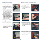
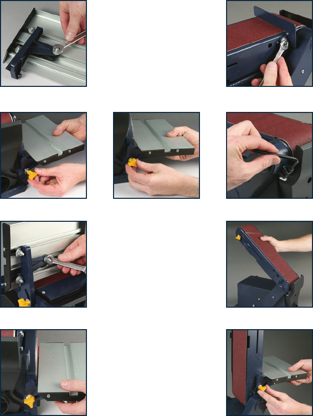
Installing table assembly
1. Position table support against
table (4) and align the holes.
2. Using 3 M6 hex screws, 3 lock
washers and 3 flat washers
fasten the table support to the
work table.
3. Position the table support in
the corresponding holes on the
side of the base. Ensure that
the 9.5 mm diameter index pin
aligns with the upper hole.
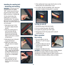
4. Place the 6.5 mm washer on
the end of the table lock knob
threaded shaft and insert shaft
through the slot and into the
threaded hole of base.
WARNING: To avoid trapping the
work of fingers between the table
and sanding surface, the table
edge should be a maximum of
1-2 mm from sanding surface.
5. Loosen the 3 hex head screws
at bottom of table support
and adjust table as required.
Adjust table as necessary and
retighten screws.
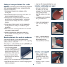
Auxiliary mounting for vertical sanding
1. Remove work support (9) lock
and bolt (10), and remove
work support.
2. Remove table assembly
by removing table lock knob
and washer.
3. Loosen the belt bed locking
screw (15) and raise the belt
sander bed (12) to the vertical
position. Retighten the locking
screw (15).
4. Attach work table assembly (4)
to auxiliary holes in belt bed.
Make sure index pin is in the
upper hole when sanding table
is in vertical position.