


10
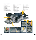
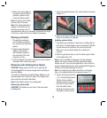
3. When set at right angles to
the planer base, the fence
provides a guide to help
control the planing action.
Note. The fence can be fitted
to either side of the base.
Note. The angle graduations
marked on the fence are for
indicative purposes only. For
accurate bevel cutting it is necessary to measure the angle
of the fence, make a trial cut and adjust if necessary.
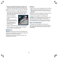
Shavings extraction
1. The dust/chip extraction
port (6) allows connection
to a vacuum dust extraction
system.
2. Using the dust extraction
adaptor (18) permits a
dust extraction system to
be connected to the dust
extraction port (6).
3. To fit the adaptor (18) insert it into the port (6) and twist it
clockwise until it locks into position.
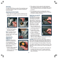
Removing and installing planer blades
CAUTION. Always ensure that the tool is switched off
and unplugged from the power supply before installing or
removing blades.
Your planer is fitted with reversible blades. Blades can be
reversed when blunt. After both sides of the blades have
been used they should be discarded.
Note: These blades cannot be re-sharpened.
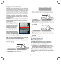
Removing a planer blade
CAUTION. The blades are very sharp. Take care when
handling them.
1. Using the supplied spanner (19), loosen the five clamping
screws (11).
2. Remove the planer blade (9) from the slot in the blade
barrel (10) in which it is retained.
Installing a planer blade
1. The blades are reversible as they have a cutting edge on
both sides. If a blade edge is worn or damaged, the blade
can be removed and put back the other way around.
Either turn over the planer blade (9) or replace it if
required.
2. Slide the good blade face up into the blade support block
of the blade barrel (10).
Note. If only one blade is damaged, it can be replaced
without the need to replace the other two blades. When
blades are worn, they must be replaced as a set of three to
prevent unbalanced operation with consequential dangerous
vibration and possible damage to the tool.
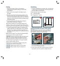
Note: The ridge along the blade should be on the blade
face on the opposite side to the clamping screws (11).
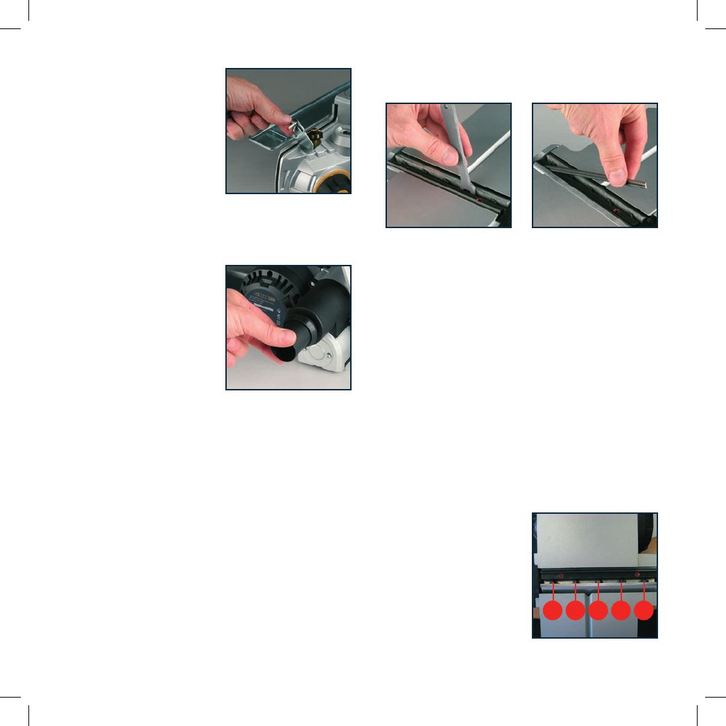
3. Tighten the clamping screws
(11), in the following manner.
Tighten the two outside
clamping screws snug tight,
then the next two screws,
then the middle screw.
Working in the same order,
fully tighten all five screws.
1
3
5
4
2
Order of tightening
clamping screws