


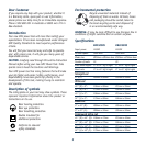

11
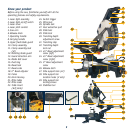
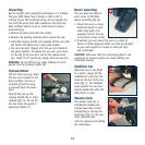
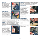
Slide lock
When tightened, the slide
lock (29) prevents the
saw head from sliding.
Tighten the slide lock during
transportation (fig. E).
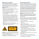
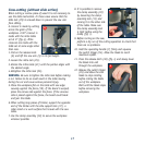
Mitre table lock
The mitre table lock (25) is
used to lock the table at the
desired mitre angle (fig. F).
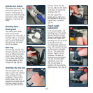
The mitre saw cuts from 0°
to 45° both left and right. To
adjust the mitre angle loosen
the mitre table lock and
using the mitre table handle
adjust the mitre angle to the desired position. The mitre
table features positive click stops at 0°, 15°, 22.5°, 30°
and 45° for quick setting of common mitre angles.
WARNING. Be sure to tighten the mitre table lock before
making a cut. Failure to do so could result in the table
moving during the cut and cause serious personal injury.
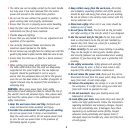
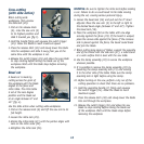
Bevel lock
The bevel lock (16) is used
to set the blade at the
desired bevel angle (fig. G).
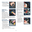
The mitre saw bevel cuts
from 0° to 45° to the left
and right. To adjust the bevel
angle loosen the bevel lock
and pull out the 0° bevel
adjuster (18). Adjust the saw
arm to the desired bevel angle.
WARNING. Be sure to tighten the bevel lock before making
a cut. Failure to do so could result in the saw arm moving
during the cut and cause serious personal injury.0°
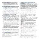
Bevel adjuster
The bevel adjuster (18)
needs to be pulled out before
the bevel angle can be
adjusted (fig. H).
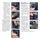
To return the saw arm to
the vertical (0° bevel)
position move the saw arm
to the left and push in the
0° bevel adjuster.
Return the saw blade to the vertical position, it will
automatically stop at the 0° bevel position. Tighten the
bevel lock.
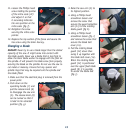
Clamp assembly
The clamp assembly (10)
can be mounted to the fence,
either side of the saw blade,
to suit the task at hand
(fig. I).
Use the clamp assembly lock
(11) at the back of the fence
to secure the clamp assembly
in position (fig. J).
E
I
J
F
G
H