


15
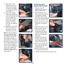
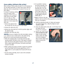
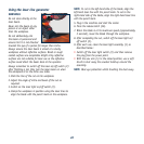
11. Loosen the Phillips head
screw holding the pointer
of the mitre scale (22)
and adjust it so that
it accurately indicates
the zero position on the
mitre scale (fig. f).
12. Retighten the screw
securing the mitre scale
pointer.
13. Replace the top section of the fence and secure the
hex screw using the 6mm hex key.
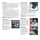
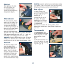
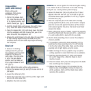
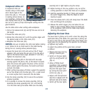
Changing a blade
DANGER! Never try to use a blade larger than the stated
capacity of the saw. It might come into contact with
the blade guards. Never use a blade that is too thick to
allow the outer blade washer to engage with the flats on
the spindle. It will prevent the blade screw from properly
securing the blade on the spindle. Do not use the saw to
cut metal or masonry. Ensure that any spacers and
spindle rings that may be required suit the spindle and
the blade fitted.
1. Make sure that the electrical plug is removed from the
power point.
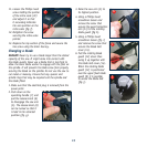
2. Push down on the
operating handle (7) and
pull the release knob (6)
to disengage the saw arm
(5). The release knob (6)
can be turned so that it
is held in the retracted
position (fig. g).
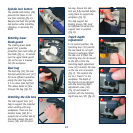
3. Raise the saw arm (5) to
its highest position.
4. Using a Phillips head
screwdriver loosen and
remove the screw that
secures the guard retraction
arm (13) to the rotating
blade guard (fig h).
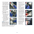
5. Using a Phillips head
screwdriver loosen (fig. i)
and remove the screw that
secures the blade bolt
cover (14).
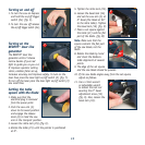
6. Pull the rotating blade
guard (12) down then
swing it up together with
the blade bolt cover (14).
When the rotating blade
guard (12) is positioned
over the upper fixed blade
guard (9) it is possible
to access the blade bolt
(fig. j).
g
i
h
f
j