


9
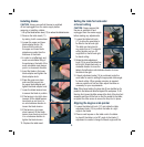
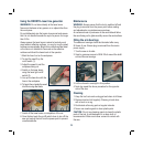
Installing blades
CAUTION. Always ensure that the saw is switched
off and unplugged from the mains supply before
removing or installing a blade.
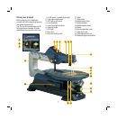
1. Lift up the blade tension lever (12) to reduce the blade tension.
2. Remove the table insert (11)
by raising it with a screwdriver.
3. Loosen the upper and lower
blade adapter knobs (14).
Ensure that the slots on
the upper and lower blade
adapters are wider than the
thickness of the blade.
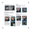
4. In order to cut effectively and
avoid uncontrollable lifting of
the workpiece, the teeth of the
scroll saw blade must always
point in a downward direction.
5. Insert the blade in the lower
blade adapter and tighten the
blade adapter knob.
6. Press the upper arm down
and insert the top part into
the upper blade adapter and
tighten the blade adapter knob.
7. Lower the blade tension lever
to secure the blade in position.
8. If the tension is too tight when
lowered, lift the blade tension
lever back up and turn it in
an anti-clockwise direction to
loosen the blade tension.
9. If the tension is too loose
when lowered, lift the blade
tension lever back up and turn
it in a clockwise direction to
tighten the blade tension.
10. Replace the table insert.
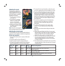
Setting the table for horizontal
or bevel cutting
CAUTION. Always ensure that
the saw is switched off and
unplugged from the mains supply
before making any adjustments.
1. Loosen the table lock knob
(17) to allow the saw table to
be tilted to the left and right.
The table can be locked at
any angle from a 0º horizontal
cutting position up to a 45º
angle both to the left and right
for bevel cutting.
2. Rotate the table adjustment
knob (18) to move the table from
left to right. Rotate the knob in a
clockwise direction to move the
table to the left and an anti-clockwise direction to move
the table to the right.
3. A bevel adjustment scale (16) is positioned under the
work table to assist in setting the appropriate table angle
for bevel cutting. When greater precision is required,
make a practice cut first and then adjust the table as
necessary for your requirements.
Note. When bevel cutting, the drop foot (8) can be tilted so it’s
parallel to the table and rests flat against the workpiece. To tilt
the drop foot, loosen the Allen screw at the front of the drop foot
assembly and then tilt the foot so that it’s parallel to the table,
re-tighten the Allen screw to secure the drop foot in place.
Aligning the degree scale pointer
1. Loosen the table lock knob (17) and rotate the table
adjustment knob (18) to position the table at a right
angle to the blade.
2. Place a small square on the table next to the blade
to check if the table is at a 90º angle to the blade. If
adjustment is needed, change the bevel angle until the