


309662 19
Engine
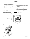
Removal
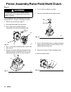
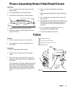
1. Remove Pinion Assembly/Rotor/Field/Pinion/
Clutch, Clamp and Clutch Housing,asin-
structed on pages 16, 17, and 18.
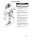
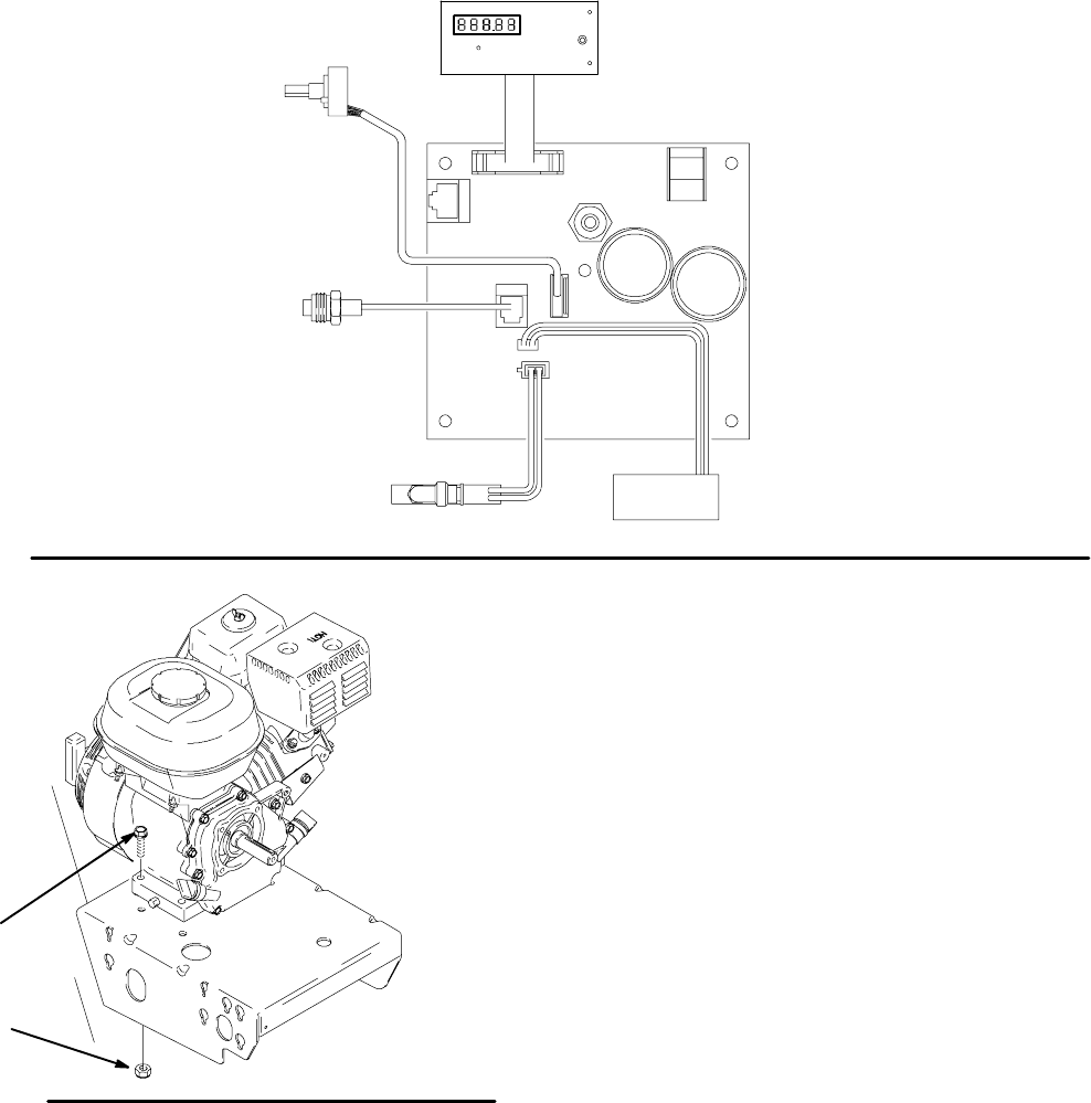
2. Fig. 17. Disconnect all necessary wiring.
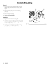
3. Fig. 18. Remove two locknuts (18) and
screws (17) from base of engine.
4. Lift engine carefully and place on work bench.
NOTE: All service to the engine must be performed by
an authorized HONDA dealer.
Installation
1. Lift engine carefully and place on cart.
2. Fig. 18. Install two screws (17) in base of engine
and secure with locknuts (18). Torque to 200 in-lb
(22.6 NSm).
3. Fig. 17. Connect all necessary wiring.
4. Install Pinion Assembly/Rotor/Field/Pinion/
Clutch, Clamp and Clutch Housing,as
instructed on pages 16 and 17 and 18.
SPRAYER WIRING DIAGRAM
Fig. 17
6Wires
Red, Yellow, Green,
Blue, White, Black
2X Red
2X Black
TI3110A
Transducer
Air valve
Flow sensor regulator
Flow control
Fig. 18
71
70
8710A