


307–758 25
MOTOR
BRUSH
REPLACEMENT
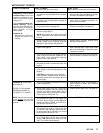
NOTE: Replace the brushes when they have worn to
less
than 1/2 in. See STEP 1, Fig 25–3. Note that
the
brushes wear dif
ferently
on each side of the
motor, so check them both. Brush Repair Kit
220–853 is available. A new spring clip, P/N
110–816
may be purchased separately
.
WARNING
To
reduce the risk of serious injury
, follow the illus
-
trated Pressure Relief Procedure warning on
page 24 whenever you are instructed to relieve
pressure.
NOTE: Read the GENERAL REPAIR INFORMATION
on
page 24 before doing this procedure.
1.
Relieve pressure.
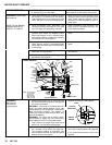
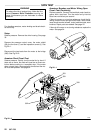
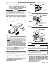
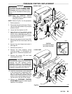
2. Remove the motor shield (58). Remove the inspec-
tion covers (J) and gaskets (K) on each side of the
motor.
See Fig 25–1.
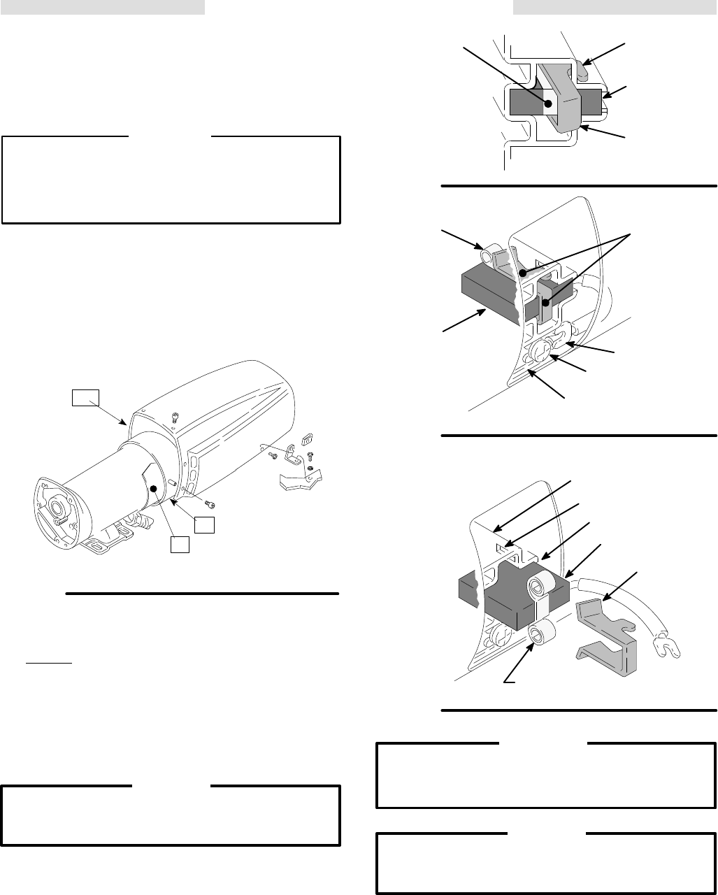
Fig 25–1
01577
J
F
58
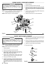
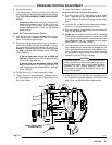
3. Push in the spring clip to release its hooks from the
brush
holder
. Pull out the spring clip. See Fig 25–2.
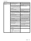
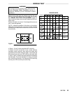
4. Loosen
the brush lead terminal screw
. Pull the brush
lead away, leaving the motor lead terminal in place.
Remove the brush and spring. See Fig 25–3.
5. Inspect the commutator for excessive pitting, burn-
ing or gouging. A black color on the commutator is
normal.
Have the commutator resurfaced by a quali
-
fied motor repair shop if the brushes seem to wear
too
fast.
CAUTION
When installing the brushes, follow all steps care-
fully to avoid damaging the parts.
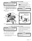
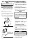
6. Install a new brush so the lead is in the long slot of
the
holder
. See Fig 25–4.
7. Slide the terminal under the terminal screw washer
and
tighten the screw
. Be sure the motor lead is still
connected
at the screw
. See Fig 25–3.
8. Place
the spring on the brush as shown in Fig 25–4.
9. Install the spring clip and push it down to hook the
short
slots in the housing. See Fig 25–4.
10.
Repeat for the other side.
BRUSH
Fig 25–2
SPRING
BRUSH
LEAD
TERMINAL SCREW
MOT
OR LEAD
TERMINAL
SPRING CLIP
P/N 1
10–816
HOOK
Fig
25–4
BRUSH
SHORT
SLOT
LONG SLOT
BRUSH HOLDER
NOTE: SPRING MUST COIL
IN THIS DIRECTION
Fig
25–3
SPRING
CLIP
BRUSH
SPRING
CLIP
SPRING
01227
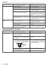
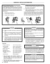
Do not touch the brushes, leads, springs or brush
holders
while the sprayer is plugged in
to reduce the
risk
of electric shock and serious bodily injury
.
WARNING
CAUTION
Do not run the sprayer dry for more than 30 sec-
onds while checking the brushes to avoid damag-
ing the displacement pump packings.
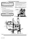
11. Test the brushes. With the sprayer OFF, turn the
pressure
control knob to minimum pressure. Plug in
the sprayer. Turn the sprayer ON. Slowly increase
the
pressure until the motor comes up to full speed.
Inspect the brush and commutator contact area for
excessive arcing. Arcs should not “trail” or circle
around
the commutator surface.
12.
Install the remaining parts.